
Variable speed constant frequency dual-feed asynchronous wind power generator rotor current non-delay control method

A wind turbine and rotor current technology, applied in the direction of generator control parts, generator control, control system, etc., can solve the problem that the circuit cannot distinguish whether the grid voltage is balanced or unbalanced, which affects the dynamic control performance and dynamic control effect of the system Unsatisfactory problems, etc., to achieve the effect of improving uninterrupted operation (traveling) capability, simple and easy control method, and good dynamic response characteristics

Inactive Publication Date: 2008-03-12
ZHEJIANG UNIV
View PDF1 Cites 41 Cited by
  • Summary
  • Abstract
  • Description
  • Claims
  • Application Information

AI Technical Summary

Problems solved by technology

In addition to the delay introduced during the separation, the bandwidth of the control system will be affected, which will cause dynamic tracking errors and the dynamic control effect is not ideal
What's more, the circuit cannot distinguish whether the grid voltage is balanced or unbalanced, and whether positive and negative sequence system decomposition is required
If DFIG operates in a state of strict grid voltage balance, the control system will still use a notch filter to separate the rotor variable, which will bring unnecessary delay to the normal control of the system and seriously affect the dynamic control performance of the system

Method used


Image

  • Variable speed constant frequency dual-feed asynchronous wind power generator rotor current non-delay control method
  • Variable speed constant frequency dual-feed asynchronous wind power generator rotor current non-delay control method
  • Variable speed constant frequency dual-feed asynchronous wind power generator rotor current non-delay control method

Examples


Embodiment Construction

[0034] The present invention will be further described below in conjunction with the accompanying drawings and implementation examples.

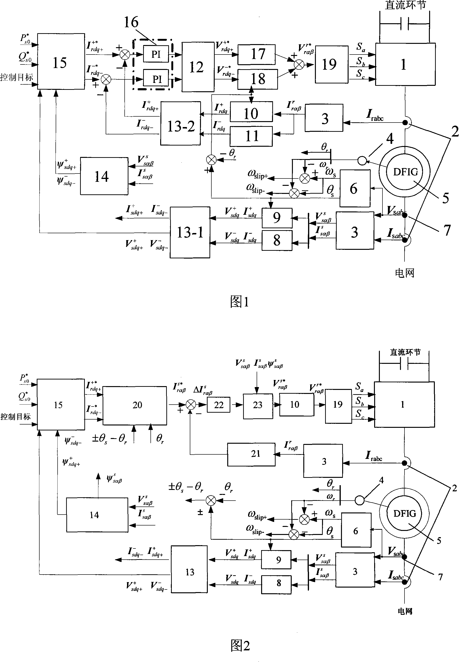
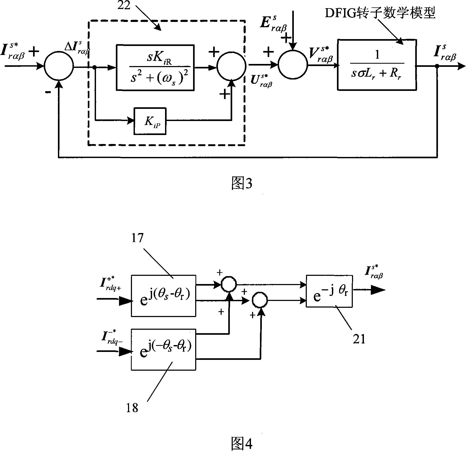
[0035] Fig. 2 is a schematic diagram of the variable-speed constant-frequency doubly-fed asynchronous wind generator rotor current without delay control method proposed by the present invention, including the control object DFIG5 and the rotor-side converter 1 (two-level or three-level) connected to the DFIG rotor Flat voltage type PWM inverter), Hall sensor 2 for three-phase stator and rotor current detection and Hall sensor 7 for three-phase stator voltage detection, encoder 4 for detecting DFIG rotor position and speed, and realizing Control loop of DFIG control target under unbalanced grid voltage condition. The control loop is composed of a feedback signal processing channel and a forward control channel, wherein the feedback signal processing channel includes a software phase-locked loop (PLL) 6 for detecting the grid voltage phase and...


PUM


Abstract

The invention discloses a nondelay control method for the current of the rotor of the variable speed constant frequency double feed nonsynchronous aerogenerator(DFIG). The switch of the rotational coordinate is finished by collecting three phase rotor current signal so as to obtain the rotor current feedback amount in the static frame of axes to compare with the rotor current command in the stator static frame of axes, the difference signal is input into the proportion-resonance regulator for comparison, the rotor voltage reference value in the stator static fame of axes is obtained after feedback compensation decoupling. The rotor voltage reference value is then transformed into reference signals for space vector pulse width regulation in the rotor frame axes to generate switch signals of the power components of the converter of the rotor to control the synchronize and close operation of the generator. The invention is needless of the break down of the positive and negative sequence of current of the EFIG rotor no matter the electric net voltage is balance or not without introducing break down delay. The invention can realize strengthened control of the generating system in imbalanced electric net, effectively improve non-stop operation of the aerogenerator.

Description

technical field [0001] The invention relates to a method for controlling the rotor current of a wind power generator, in particular to a variable-speed constant-frequency doubly-fed asynchronous wind power generator ( DFIG) rotor current without delay control method. Background technique [0002] Modern large-scale wind power generation systems mainly include double-fed asynchronous generators (DFIG) and permanent magnet synchronous generators. In order to improve power generation efficiency, variable-speed constant-frequency power generation operations are implemented, and the DFIG system is the current mainstream model. At present, my country's wind power technology mostly stays in the operation control under ideal grid conditions. Since the actual grid often has various symmetrical and asymmetrical faults, it is necessary to carry out research on operation control under grid faults and propose corresponding control methods. In recent years, the research on DFIG wind powe...

Claims


Application Information

Patent Timeline
IPC IPC(8): H02P9/00H02P9/02
Inventor 胡家兵贺益康
Owner ZHEJIANG UNIV
Learn More