
Tube-type electric motor

A tubular motor, tubular technology, applied in electrical components, electromechanical devices, mechanical equipment, etc., to achieve the effects of simplified structure, low energy consumption, and reasonable overall structure layout

Inactive Publication Date: 2008-03-12
KELIYA MACHINE TECH SHANGHAI
View PDF0 Cites 3 Cited by
  • Summary
  • Abstract
  • Description
  • Claims
  • Application Information

AI Technical Summary

Problems solved by technology

[0006] The technical problem to be solved by the present invention is to provide a high-performance tubular motor with low energy consumption, sensitive braking, compact structural design of each part, strong independence, and reasonable overall structure layout, so as to overcome the shortcomings of existing tubular motors

Method used


Image

  • Tube-type electric motor
  • Tube-type electric motor
  • Tube-type electric motor

Examples


Embodiment Construction

[0040] In order to make the technical means, creative features, goals and effects achieved by the present invention easy to understand, the present invention will be further described below in conjunction with specific embodiments.

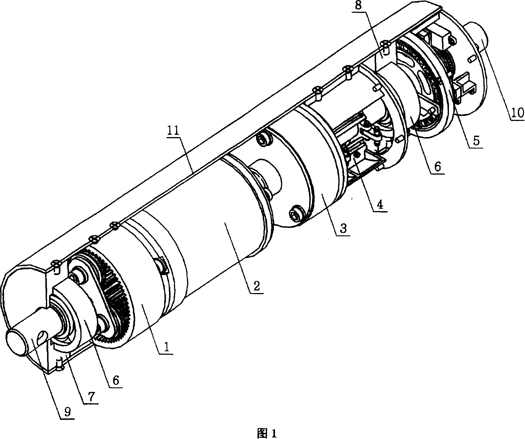
[0041] Referring to Fig. 1, a tubular motor includes a tubular casing 11 and a drive assembly supported in the tubular casing 11 through a bearing seat, a brake assembly and a stroke control assembly. The drive assembly consists of a small volume, low speed, large The low-speed motor 2 of the torque and the single-stage planetary gear transmission mechanism 1 driven by the low-speed motor 2 constitute.

[0042] The low-speed motor 2 is a permanent magnet synchronous motor that directly obtains a low speed by the motor without a reduction gear device. Or a low-speed DC servo motor composed of a multi-stage special steel reducer and a servo DC motor.

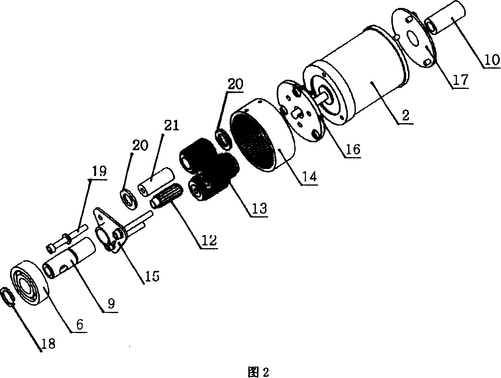
[0043] Referring to Fig. 2, the single-stage planetary gear transmission mechanism 1 that it adop...


PUM


Abstract

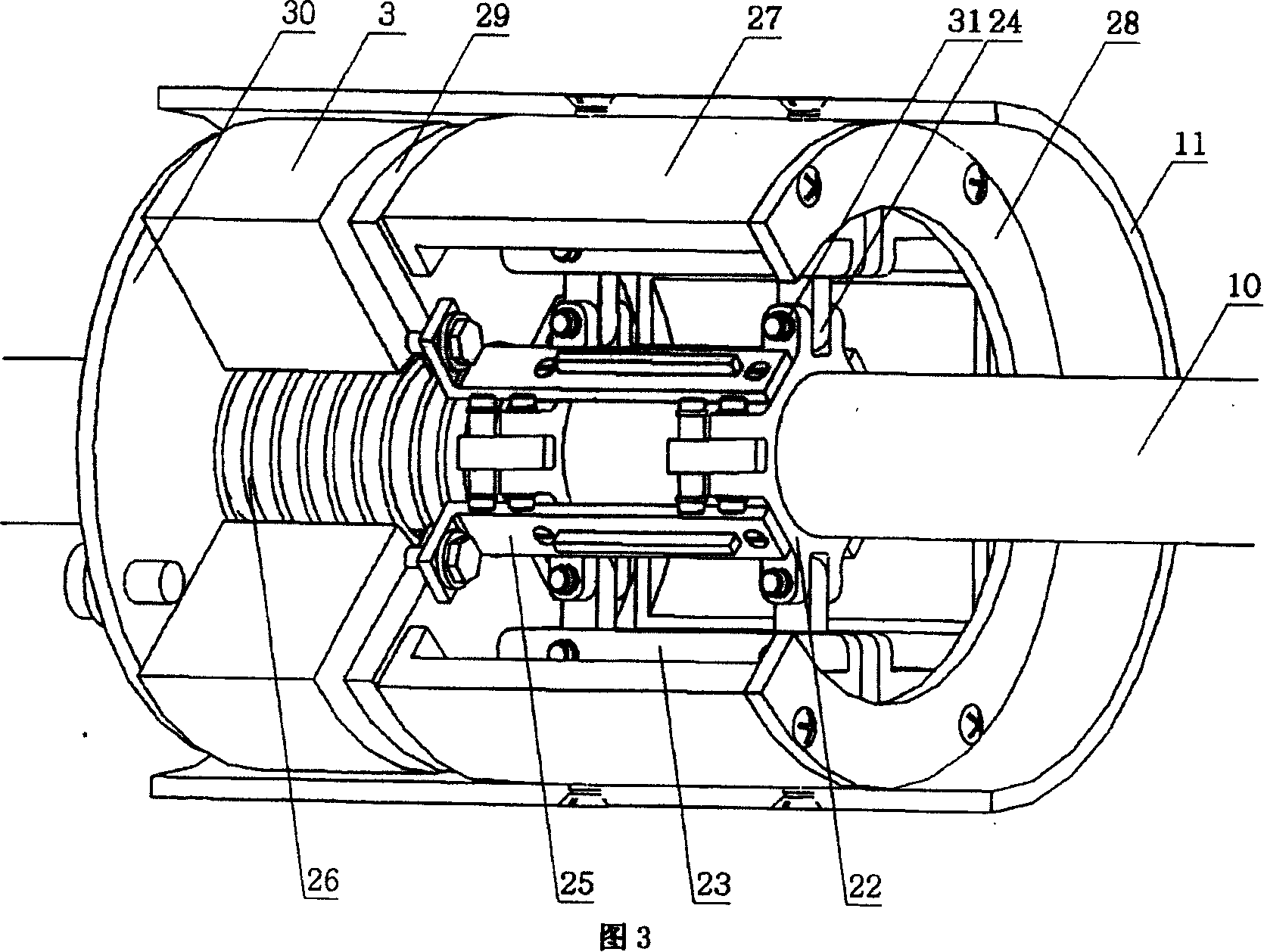
The invention relates to a high performance tubular electric machine, comprising a tubular engine casing, and a drive assembly, a brake assembly and a travel control assembly which are supported in the tubular engine casing by a beari9ng seat; wherein the brake assembly comprises an electric machine right axis securing fitting, a right axis, an electromagnet right axis securing fitting, an electromagnet and a leverage braking mechanism; The electric machine right axis securing fitting is fixed at the right end surface of the low-speed electric machine and used for supporting one end of the right axis; the electromagnet right axis securing fitting is fixed at the right axis, the electromagnet is fixed at the electromagnet right axis securing fitting; the leverage braking mechanism is arranged at the right axis and arranged in the cavity which is arranged between the right axis and the tubular engine casing, the electromagnet drives the leverage braking mechanism to break. Trough the connecting-rod principle, the invention increase the elasticity of the pressure spring to reduce the power of the electromagnet, thereby the invention has the advantages of low energy consumption, quick starting, novel design of the brake assembly, rational structure, quick break speed, good break effect and long service time, therefore, the invention is capable of being widely used in various products such as dynamo-electric dropping door, sunshade system and projection screen, etc.

Description

technical field [0001] The invention relates to a motor, in particular to a tubular motor with a slender structure. Background technique [0002] Tubular motors are more and more used in products such as rotating curtain doors and windows, sunshade systems, projection screens and other products that can be electrically lifted and lowered. They have the advantages of convenient operation and strong modern sense. Most of the existing tubular motors use a driving device combining a high-speed motor and a three-stage planetary gear reducer. Such a driving device has the problems of high frictional resistance and high cost due to the large number of gears in the reducer. [0003] Most of the current tubular motors use compression springs to directly compress the brake pads, which requires a large electromagnet power and produces insufficient braking friction, resulting in high energy consumption of the system and poor braking effect. In the braking system, the braking system use...

Claims


Application Information

Patent Timeline
Patent Type & Authority Applications(China)
IPC IPC(8): H02K7/10H02K7/102F16D65/27H02K7/116F16D65/22
Inventor 黄凯宇高瞻
Owner KELIYA MACHINE TECH SHANGHAI
Learn More