
Control method of DC side-discharging circuit of full power convertor

A technology of unloading circuit and DC side voltage, which is applied in the direction of output power conversion device, conversion equipment for intermediate conversion to DC, emergency protection circuit device, etc., which can solve the problem of affecting the service life of DC side capacitors and DC side voltage fluctuations. , DC side voltage ring is difficult to match and other issues

Inactive Publication Date: 2010-06-09
INST OF ELECTRICAL ENG CHINESE ACAD OF SCI +1
View PDF4 Cites 4 Cited by
  • Summary
  • Abstract
  • Description
  • Claims
  • Application Information

AI Technical Summary

Problems solved by technology

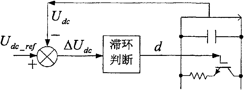
The advantages of these two methods are that the control is simple and the response speed is fast, but only the DC side voltage is used as the judgment condition, and it is difficult to cooperate with the DC side voltage loop of the grid side converter. It must be determined when the DC side voltage is higher than a certain value unloading circuit will work, so these methods, especially Figure 1a The method will cause large fluctuations in the DC side voltage and affect the service life of the DC side capacitor

Method used


Image

  • Control method of DC side-discharging circuit of full power convertor
  • Control method of DC side-discharging circuit of full power convertor
  • Control method of DC side-discharging circuit of full power convertor

Examples


Embodiment Construction

[0021] The present invention will be further described below in conjunction with the accompanying drawings and specific embodiments.

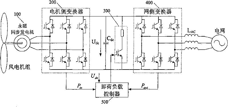
[0022] figure 2 Shown is the application object of the present invention, a direct-drive variable-speed constant-frequency wind power system. Firstly, the structure of the direct-drive variable-speed constant-frequency wind power system will be described. Such as figure 2 As shown, the wind turbine drives the permanent magnet synchronous generator 100, the alternating current generated by the permanent magnet synchronous generator 100 is rectified by the generator side converter 200 to obtain direct current, and the DC side capacitor C dc To stabilize the DC side voltage, the unloading circuit 300 acts as a protection device for the overvoltage of the DC side, and the grid side converter 400 inverts the DC power into AC power, which is connected to the grid through the grid side filter inductor. Among them, the permanent magnet synchronous...


PUM


Abstract

This invention relates to a control method for off-load circuit at the DC side of a full power converter, in which, the off-load circuit is composed of a power device and an off-load resistor, the off-load circuit controller matches with the DC side voltage outer ring of the DC side of the converter of the network side to keep the DC side voltage stable by collecting input active power, outputtingthe active power and DC side voltage to take the deviation of the power as the main control condition of the off-load circuit and take the DC side voltage as the assistant control condition when thenetwork voltage is faulty.

Description

technical field [0001] The invention relates to a control method for a direct-current side unloading circuit of a full-power converter, in particular to a control method for a direct-drive type variable-speed constant-frequency wind power generation system full-power converter direct-current side unloading circuit control method. Background technique [0002] With the increasing scale of wind power generation, the impact of grid-connected wind power systems on the power grid is increasing. At present, some countries that are leading in the development of wind power technology, such as Denmark and Germany, have successively formulated new grid operation guidelines. The off-grid conditions of the wind power system are given (such as the minimum voltage drop depth and drop duration), and only when the grid voltage drops below the specified curve can the wind turbine be allowed to go off-grid, so the wind power system is required to have a strong low-voltage ride-through (LVRT) ...

Claims


Application Information

Patent Timeline
Patent Type & Authority Patents(China)
IPC IPC(8): H02M1/32H02M5/44H02H7/122
Inventor 李建林胡书举许洪华
Owner INST OF ELECTRICAL ENG CHINESE ACAD OF SCI
Learn More