Blocked scan rebuilding and space assembly method of large object image-forming with cone-beam CT
A block scanning, large object technology, used in the field of medical instruments
- Summary
- Abstract
- Description
- Claims
- Application Information
AI Technical Summary
Problems solved by technology
Method used
Image

Examples
specific Embodiment 1
[0070] Specific embodiment 1: the block local reconstruction of Shepp-Logan mould, as shown in Figure 10:
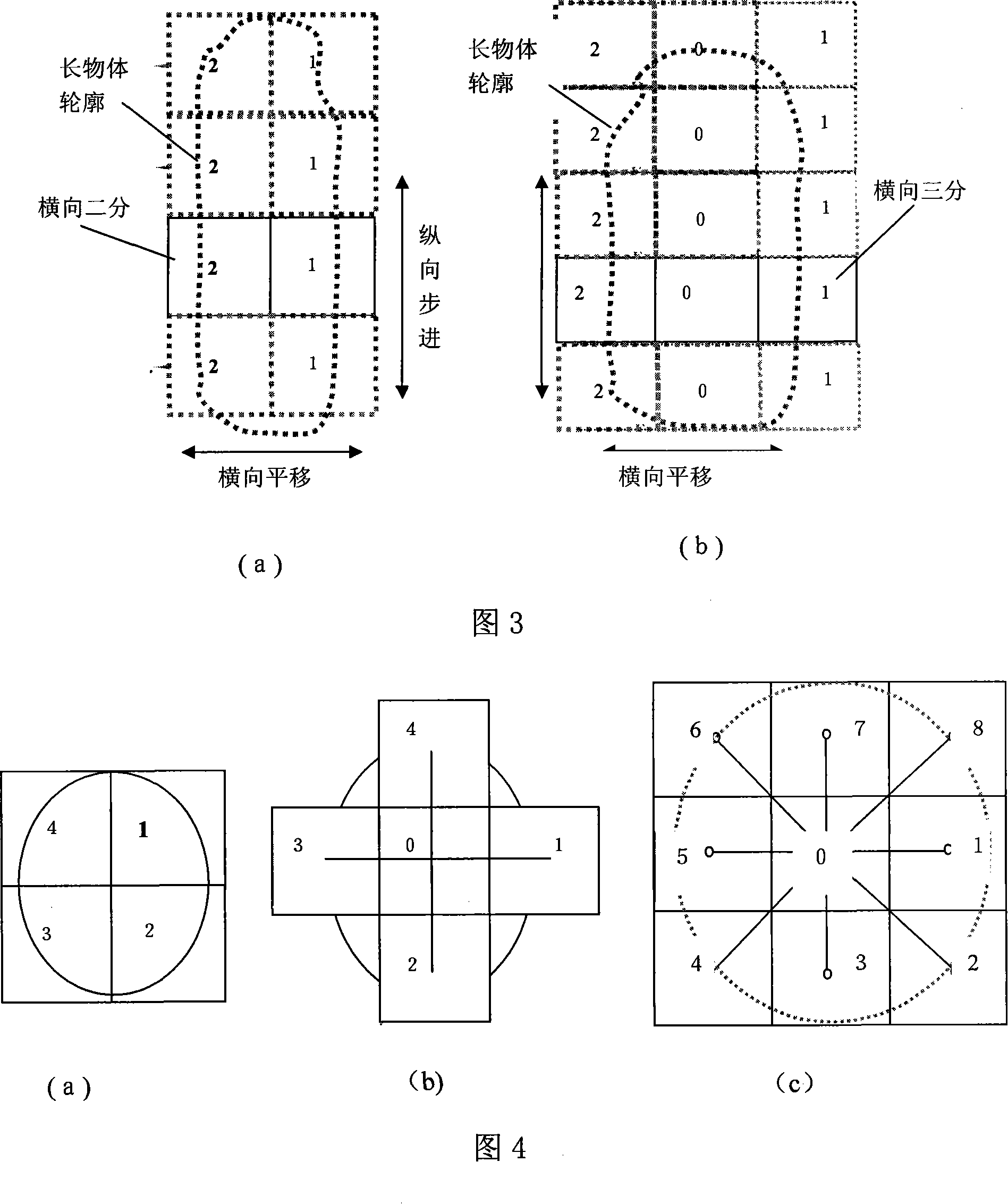
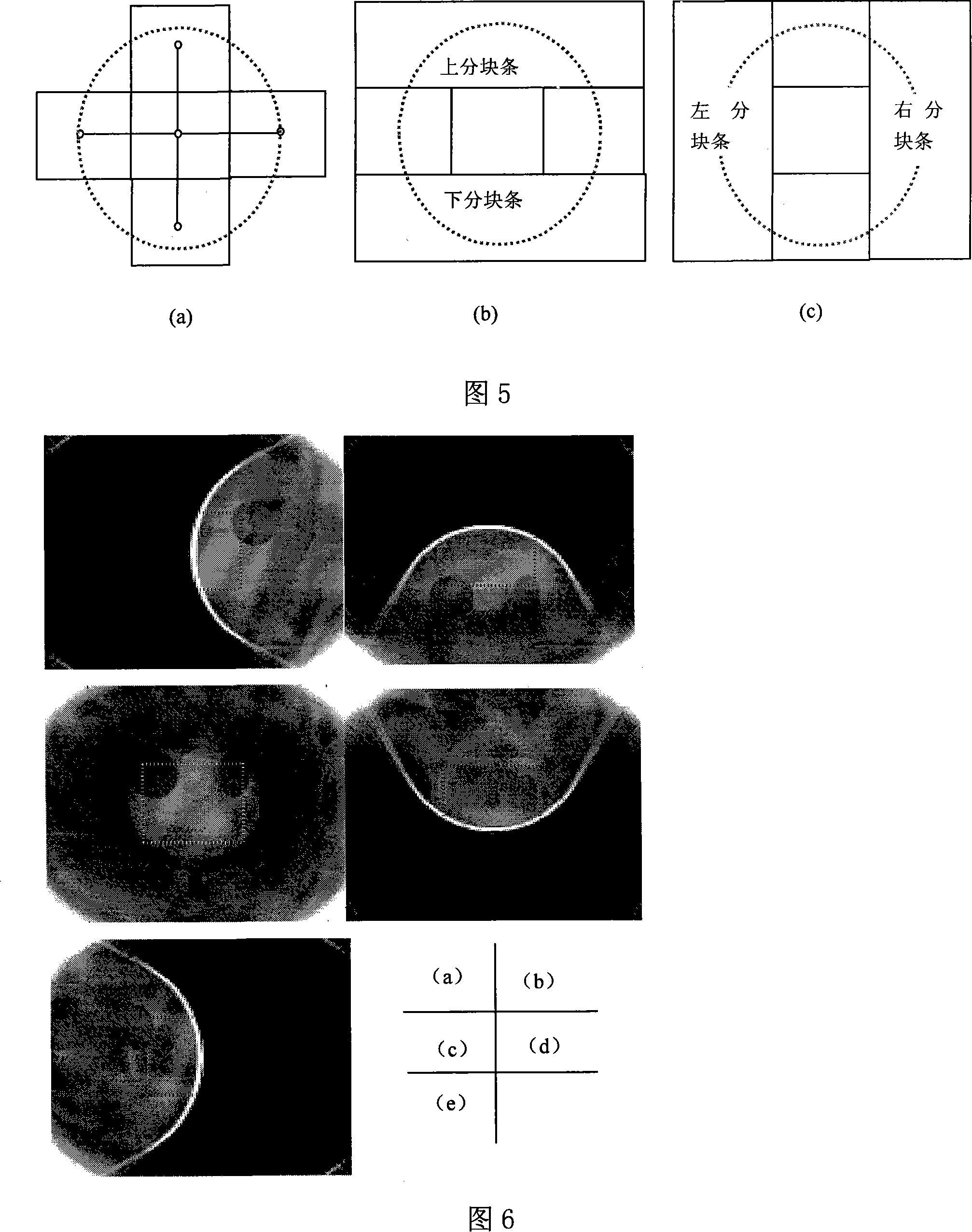
[0071] Step 1. Divide the Shepp-Logan mold into 5 blocks, as shown in Figure 5;
[0072] Step 2. Place each block area of the Shepp-Logan mold in the scanning field of view of cone beam CT, that is, the rotation center area of the turntable, and place each block area in sequence in the scanning field of cone beam CT by using the method of spatial translation field of view;
[0073] Step 3: Cone beam scanning is performed on each partition of the Shepp-Logan mold to obtain cone beam projection images. A full scan acquires about 300 projection images. Half scans acquire about 160 images.
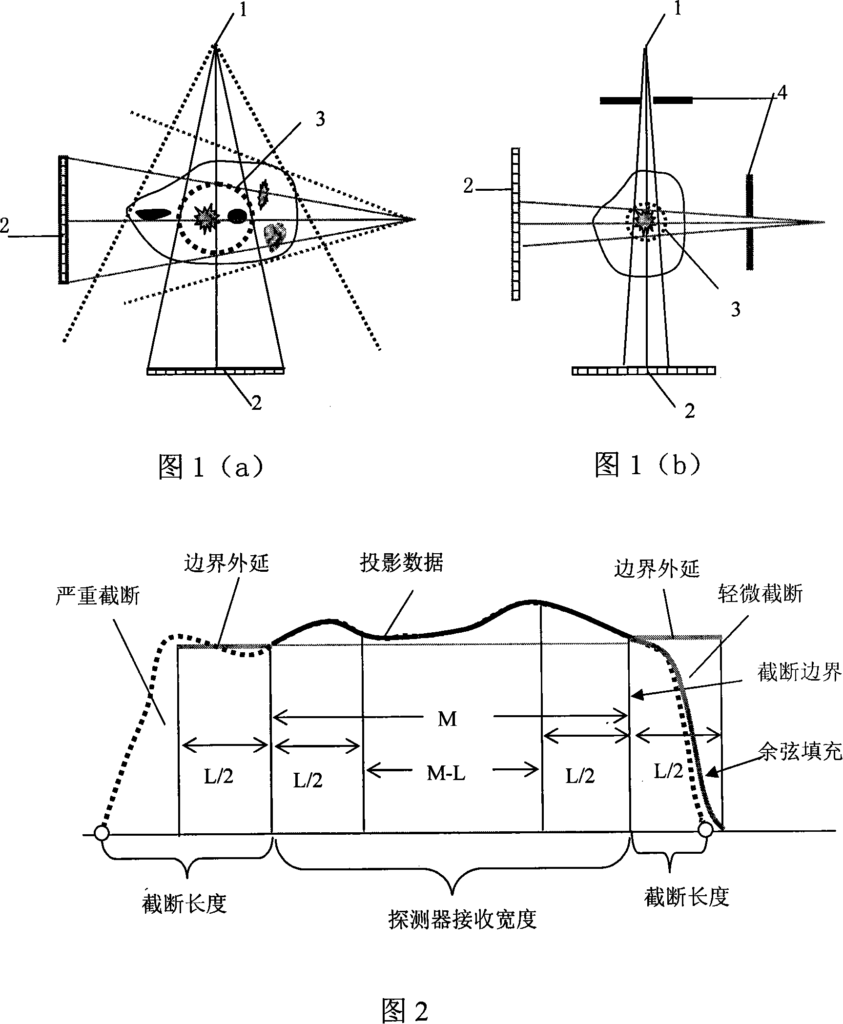
[0074] Step 4, filling the truncated area of the projected image, as shown in Figure 2;
[0075] Step 5. Use the FDK method or the convolutional back-projection method to perform 3D volume reconstruction. In this embodiment, the convolutional back-projection method is used to r...
specific Embodiment 2
[0078] Specific embodiment 2: filling the data of the projected truncated image of the breast mold;
[0079] Figure 8(a) Cone beam projection image without transverse truncation of the breast mold; Figure 8(b) Transverse truncated projection image caused by adjusting the ray collimator; Figure 8(c) Transverse truncated projection after boundary extension filling image.
[0080] Figure 9 is the local reconstruction image of the breast mold; the first row shows the local reconstruction of the transverse truncated projection without filling (see Figure 8(b)), and the Gibbs effect caused by the boundary truncation can be seen, that is, the reconstruction Very bright edges in the image; the second row shows the local reconstruction after filling the laterally truncated projection (see Fig. 8(c)), where the Gibbs effect is reduced and the reconstruction performance is improved near the border .
PUM
 Abstract
Description
Claims
Application Information
 - R&D
- Intellectual Property
- Life Sciences
- Materials
- Tech Scout
- Unparalleled Data Quality
- Higher Quality Content
- 60% Fewer Hallucinations
Browse by: Latest US Patents, China's latest patents, Technical Efficacy Thesaurus, Application Domain, Technology Topic, Popular Technical Reports.
© 2025 PatSnap. All rights reserved.Legal|Privacy policy|Modern Slavery Act Transparency Statement|Sitemap|About US| Contact US: help@patsnap.com