Strip threading method and strip threading device
A belt threading and threading technology, which is applied in transportation and packaging, thin material processing, printing, etc., can solve the problem of low work efficiency and achieve the effect of preventing tearing or damage
- Summary
- Abstract
- Description
- Claims
- Application Information
AI Technical Summary
Problems solved by technology
Method used
Image
Examples
no. 1 Embodiment approach
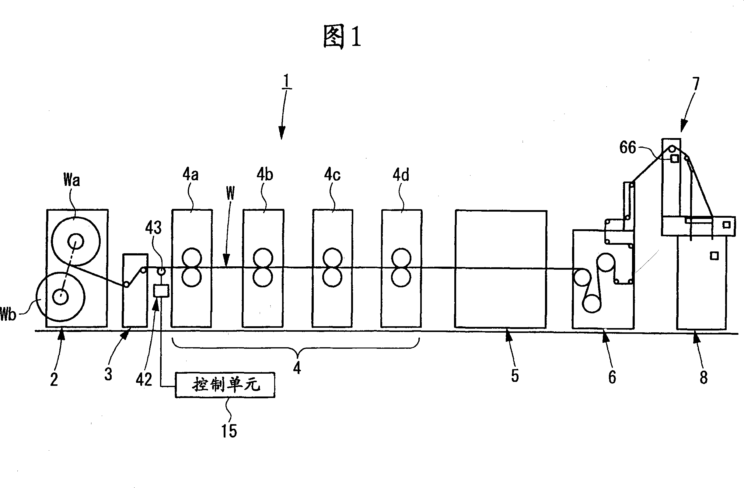
[0047] Embodiments of the belt threading method and the device using the method of the present invention will be described in detail with reference to the accompanying drawings. Hereinafter, an embodiment of a web rotary printing machine applied to printing a web as a tape will be described. This embodiment relates to a web rotary press that automatically threads the web before the press begins its operation. The web is designed to be used by using mechanisms and information that have been pre-programmed into the press's web splicing unit and remaining web length gauge, respectively. was penetrated.
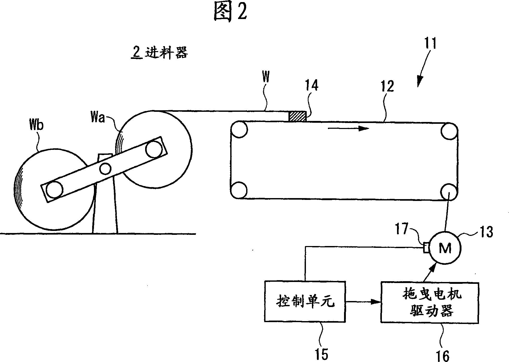
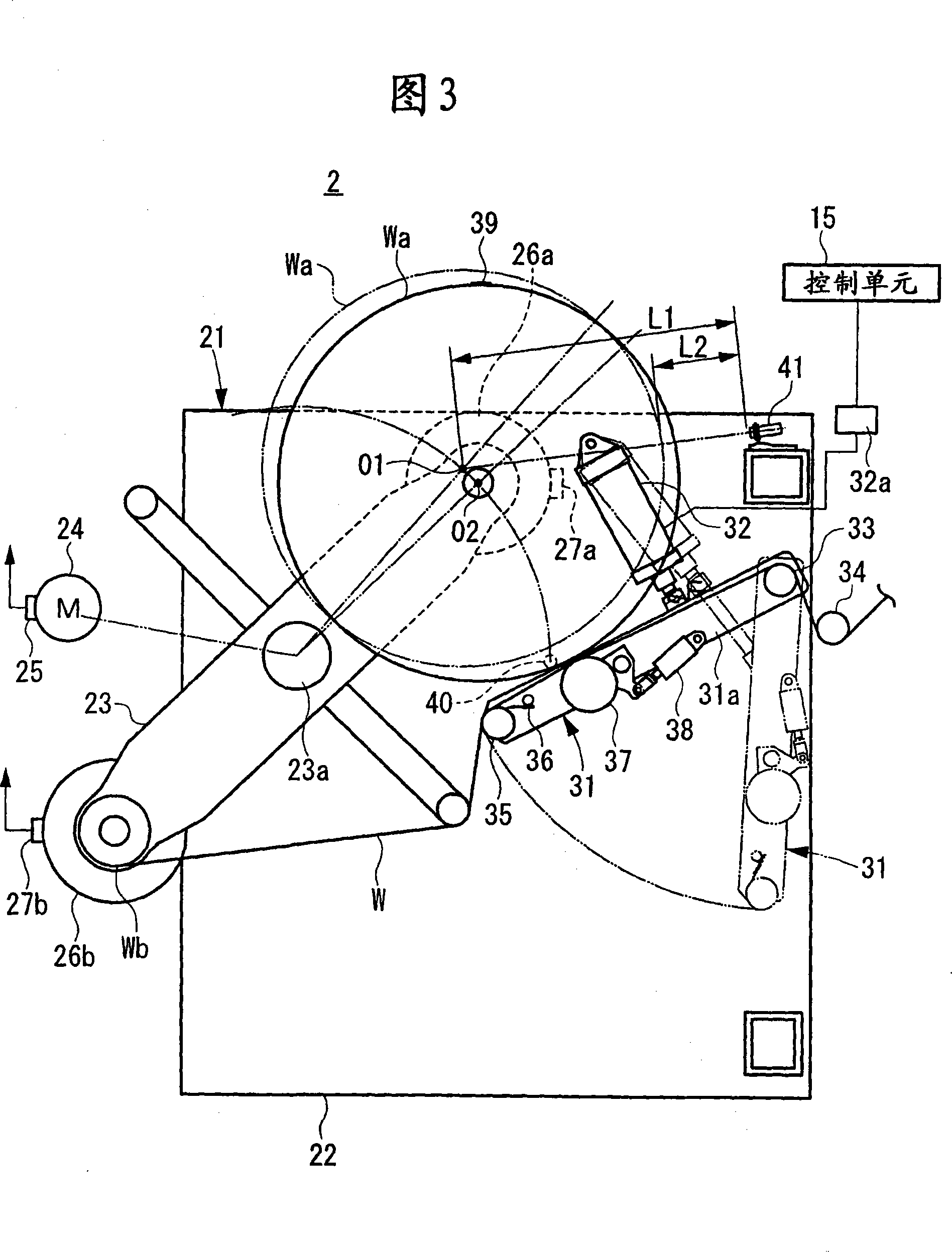
[0048] FIG. 1 shows a schematic configuration of a web rotary printing press. Fig. 2 shows a schematic diagram of the configuration of the automatic roll paper threading device. Based on these drawings, first, a schematic diagram of an arrangement of a web rotary printing press and a schematic diagram of an arrangement of an automatic web threading device will be described.
...
no. 2 Embodiment approach
[0160] Another embodiment of the present invention will be described.
[0161] The first embodiment is executed when the operator manually inputs the initial diameter of the rolled paper roll. However, such manual input work is eliminated from the second embodiment. In the second embodiment, once the process for threading the web is started, the measurement of the diameter of the web roll is automatically started.
[0162] In this embodiment, steps S1 to S12 in the flow shown in FIG. 7A are changed to steps S201 to S205 in the flow shown in FIG. 9 . The reason for this is that the measurement of the diameter of the web roll starts automatically.
[0163] Once the process starts, first, as shown in FIG. 9, it is determined whether or not the roll paper roll first selection button 81a is ON (in step S201). That is, it is determined whether or not the web roll Wa attached to the shaft of the rotary arm 23A is selected. When the roll paper roll first selection button 81a is ON...
no. 3 Embodiment approach
[0166] In the first embodiment, the tension applied to the web W during web threading is controlled by either of the web pre-drive motors 26a or 26b Rotation speed control. In contrast, in the third embodiment, the tension applied to the roll paper W during the roll paper penetration is controlled by controlling the speed at which the roll paper W is dragged by the holder 14 as the dragging member. To this end, as shown in FIG. 5B, the control system according to the third embodiment further includes: a memory 141 configured to store the corrected conveying speed of the dragging member during the roll paper passing; A memory 142 for correcting the rotational speed; a memory 143 configured to store the corrected rotational speed of the drive motor. During web threading, the corrected transport speed of the holder 14 as a dragging member is stored in the memory 141 . The corrected rotational speed for driving and rotating the holder 14 as the dragging member is stored in the m...
PUM
 Abstract
Description
Claims
Application Information
 - Generate Ideas
- Intellectual Property
- Life Sciences
- Materials
- Tech Scout
- Unparalleled Data Quality
- Higher Quality Content
- 60% Fewer Hallucinations
Browse by: Latest US Patents, China's latest patents, Technical Efficacy Thesaurus, Application Domain, Technology Topic, Popular Technical Reports.
© 2025 PatSnap. All rights reserved.Legal|Privacy policy|Modern Slavery Act Transparency Statement|Sitemap|About US| Contact US: help@patsnap.com


