
Single pole antenna

A technology of monopole antenna and radiating part, which is applied in the direction of resonant antenna, slender active unit end feed, radiating element structure, etc. It can solve the problem that the antenna is not suitable for installation, etc., and achieve small bandwidth and easy installation , compact effect

Inactive Publication Date: 2008-02-13
FOXCONN (KUNSHAN) COMPUTER CONNECTOR CO LTD +1
View PDF1 Cites 6 Cited by
  • Summary
  • Abstract
  • Description
  • Claims
  • Application Information

AI Technical Summary

Problems solved by technology

In the prior art, U.S. Patent No. US6,801,169 discloses a small dual-frequency monopole antenna, which is fixed on the PCB, wherein the radiation part is C-shaped, the grounding part is L-shaped, and the radiation part is connected by a feeder. It is connected to the ground, but the way the antenna radiating part is connected to the feeder makes this antenna unsuitable for installation in the external housing of the electronic device

Method used


Image

  • Single pole antenna
  • Single pole antenna

Examples


Embodiment Construction

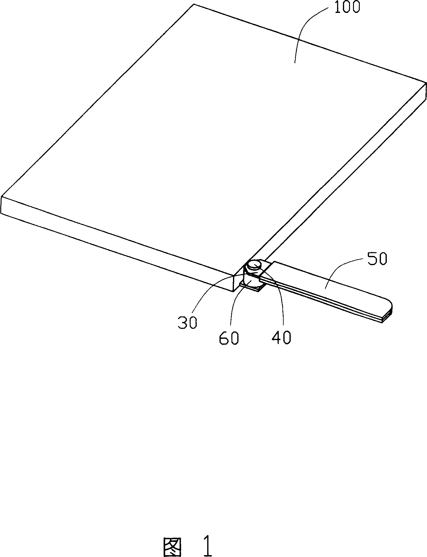
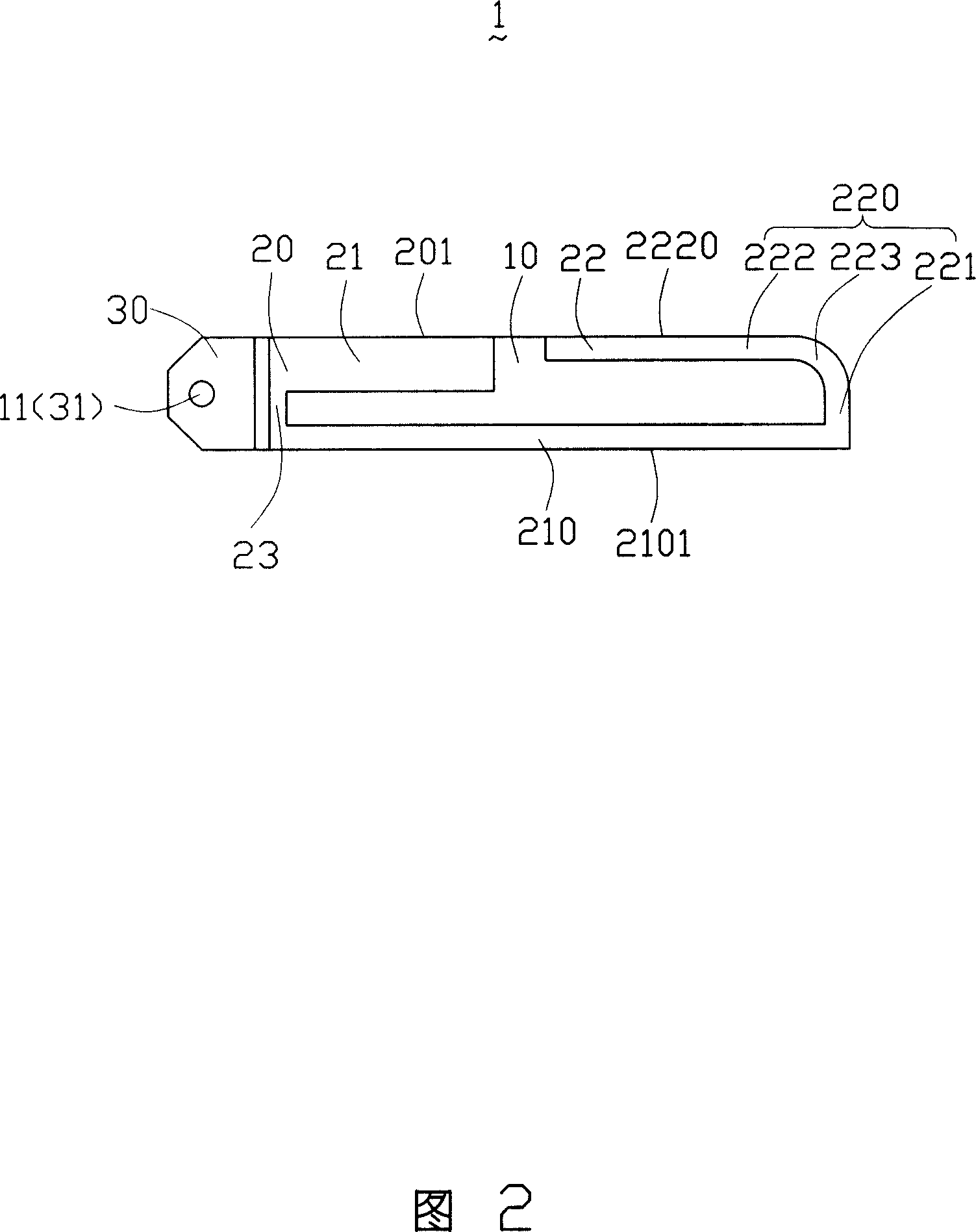
[0008] FIG. 1 and FIG. 2 show a preferred embodiment of the monopole antenna 1 of the present invention. The monopole antenna 1 is installed in an electronic device such as a notebook computer, and can be rotated and exposed to the external space. The monopole antenna 1 includes an insulating substrate 10 , a radiation portion 20 and a ground portion 30 . In this embodiment, the insulating substrate 10 is a printed circuit board and has a mounting hole 11 thereon. The radiation portion 20 and the ground portion 30 are disposed on the same surface of the insulating substrate 10 . The radiation part 20 includes a first radiation part 21 and a second radiation part 22 . The first radiating portion 21 is wider than the second radiating portion 22 , and its width can be used to adjust impedance matching, and one end of the first radiating portion 21 is connected to the second radiating portion 22 through a connecting portion 23 . The second radiating part 22 includes a first radi...


PUM


Abstract

The invention discloses a monopole antenna, which comprises an insulative baseplate having mounting holes on one end, a radiation part adhering to the insulative baseplate, and an earthing part arranged separated from the radiation part and adhering to the same face of the insulative baseplate with the radition part. The width of the radiation part is the same with the width of the printing insulative baseplate, and the radiation part is C shape.

Description

【Technical field】 [0001] The present invention relates to a monopole antenna, in particular to a monopole antenna installed outside electronic equipment. 【Background technique】 [0002] In modern electronic equipment, the use of wireless communication technology for wireless transmission of data, sound, images, etc. has been more and more used. Antenna, as a component used to induce electromagnetic waves, is a necessary device for the application of wireless communication technology equipment. In order to meet the structural requirements of different electronic devices, antennas are divided into external antennas and internal antennas. The direction of the external antenna can be adjusted by the user according to the needs, so that the antenna can send and receive signals better. The external antenna is usually a monopole antenna or a helical antenna. With the development of electronic technology, in order to adapt to the configuration of the external housing of the electr...

Claims


Application Information

Patent Timeline
Patent Type & Authority Applications(China)
IPC IPC(8): H01Q9/30H01Q9/42H01Q1/38
Inventor 戴隆盛
Owner FOXCONN (KUNSHAN) COMPUTER CONNECTOR CO LTD
Learn More