
Method for manufacturing micro-torsion shaft

A technology for twisting shafts and wafers, which is used in the manufacture of microstructure devices, microstructure technology, microstructure devices, etc., to achieve good structure, improve reliability and withstand stress.

Inactive Publication Date: 2008-02-13
TOUCH MICRO SYST TECH
View PDF0 Cites 1 Cited by
  • Summary
  • Abstract
  • Description
  • Claims
  • Application Information

AI Technical Summary

Problems solved by technology

[0008] Therefore, one of the main purposes of the present invention is to provide a method for making a micro-torsion shaft, so as to improve the insurmountable problems of known technologies

Method used


Image

  • Method for manufacturing micro-torsion shaft
  • Method for manufacturing micro-torsion shaft
  • Method for manufacturing micro-torsion shaft

Examples


Embodiment Construction

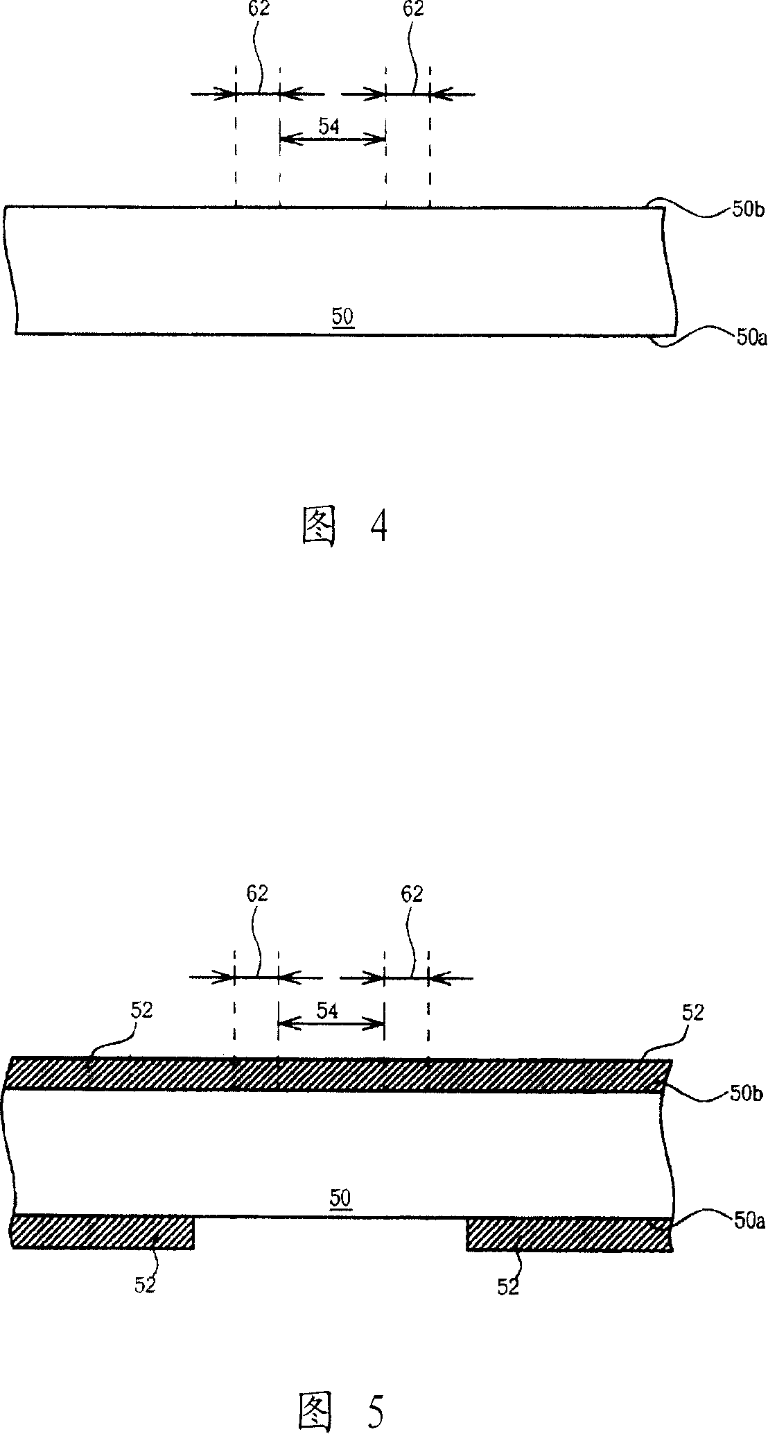
[0026] Please refer to FIGS. 4 to 12 . FIGS. 4 to 12 are schematic diagrams of a method for fabricating a micro-torsion shaft according to a preferred embodiment of the present invention. As shown in FIG. 4, a wafer 50, such as a silicon wafer, is first provided. The wafer 50 includes a first surface 50a and a second surface 50b. The second surface 50b is usually the front side of the wafer 50 and has many devices and components. The first surface 50a It is the backside of the wafer 50 . The wafer 50 defines at least one torsion axis region 54 and at least two penetration regions 62 .

[0027] As shown in FIG. 5 , an etching mask 52 is formed on the first surface 50 a and the second surface 50 b of the wafer 50 , and the etching mask 52 exposes at least the torsion axis region 54 of the first surface 50 a , and can optionally be The second penetration region 62 and the wafer 50 around the second penetration region 62 are exposed on the first surface 50a. The etching mask 52 ...


PUM


Abstract

The invention provides a method for manufacturing a micro-torsion shaft. Firstly, a wafer is provided, and at least one torsion axis area and at least two penetration areas are defined on the wafer. Afterwards, part of the wafer located in the torsion axis area is removed from the lower surface of the wafer, and the wafer located in the second penetration area is removed from the upper surface of the wafer until the wafer is penetrated to form a micro torsion axis. Next, a wafer-level measurement of the micro-torsion axis of the wafer is performed, followed by an etching process to adjust the geometry of the micro-torsion axis. According to the method of the invention, the thickness of the micro-torsion axis is no longer limited by the thickness of the wafer, and the micro-torsion axis can be measured at the wafer level.

Description

technical field [0001] The present invention relates to a method for fabricating a micro-torsion shaft, and more particularly, to a method for performing real-time wafer-level testing in a process and adjusting the characteristics of the micro-torsion shaft accordingly. Background technique [0002] Micro-electromechanical system (MEMS) technology is an emerging technology that highly integrates electronic circuits and machinery, and has been widely used in the manufacture of various electronic and mechanical components, such as micro-sensors, devices, micromotors, and optical switch components. Compared with semiconductor elements, MEMS elements often have special mechanical structures. Therefore, if the standard semiconductor process is directly used during fabrication, the resulting structures often have poor precision and cannot meet the requirements of MEMS elements. Among them, the micro-torsion shaft is a common structure in micro-electromechanical components, and si...

Claims


Application Information

Patent Timeline
IPC IPC(8): B81C1/00
Inventor 何宪龙
Owner TOUCH MICRO SYST TECH
Learn More