
Test method of sample destroy time in tube of glass fibre reinforced plastic long-term performance test

A glass steel pipe, long-term performance technology, used in measuring devices, strength characteristics, instruments, etc., can solve problems such as inability to obtain accurate time, destroying time errors, and consuming a lot of manpower and material resources

Inactive Publication Date: 2008-02-06
SHENZHEN KANGQIANG CONSTR NEW TECH ENG
View PDF0 Cites 17 Cited by
  • Summary
  • Abstract
  • Description
  • Claims
  • Application Information

AI Technical Summary

Problems solved by technology

[0007] It can be seen from Table 1 that in the early stage of the test, the frequency of observing whether the sample is damaged is very high, and a 24-hour special person is required to guard it. Although the frequency is reduced in the later period, it still needs a special person to observe regularly, and the test time is at least 10000 hours (about 417 days), which requires a lot of manpower and material resources
Even if the observation is carried out according to the requirements, the precise time of its destruction cannot be obtained, and the destruction time cannot happen exactly at the time of observation, and there is a large error between the actual destruction time and the observed destruction time

Method used


Image

  • Test method of sample destroy time in tube of glass fibre reinforced plastic long-term performance test
  • Test method of sample destroy time in tube of glass fibre reinforced plastic long-term performance test
  • Test method of sample destroy time in tube of glass fibre reinforced plastic long-term performance test

Examples


Embodiment Construction

[0025] A test method for the failure time of a sample in a long-term performance test of a glass steel pipe, which includes the following steps:

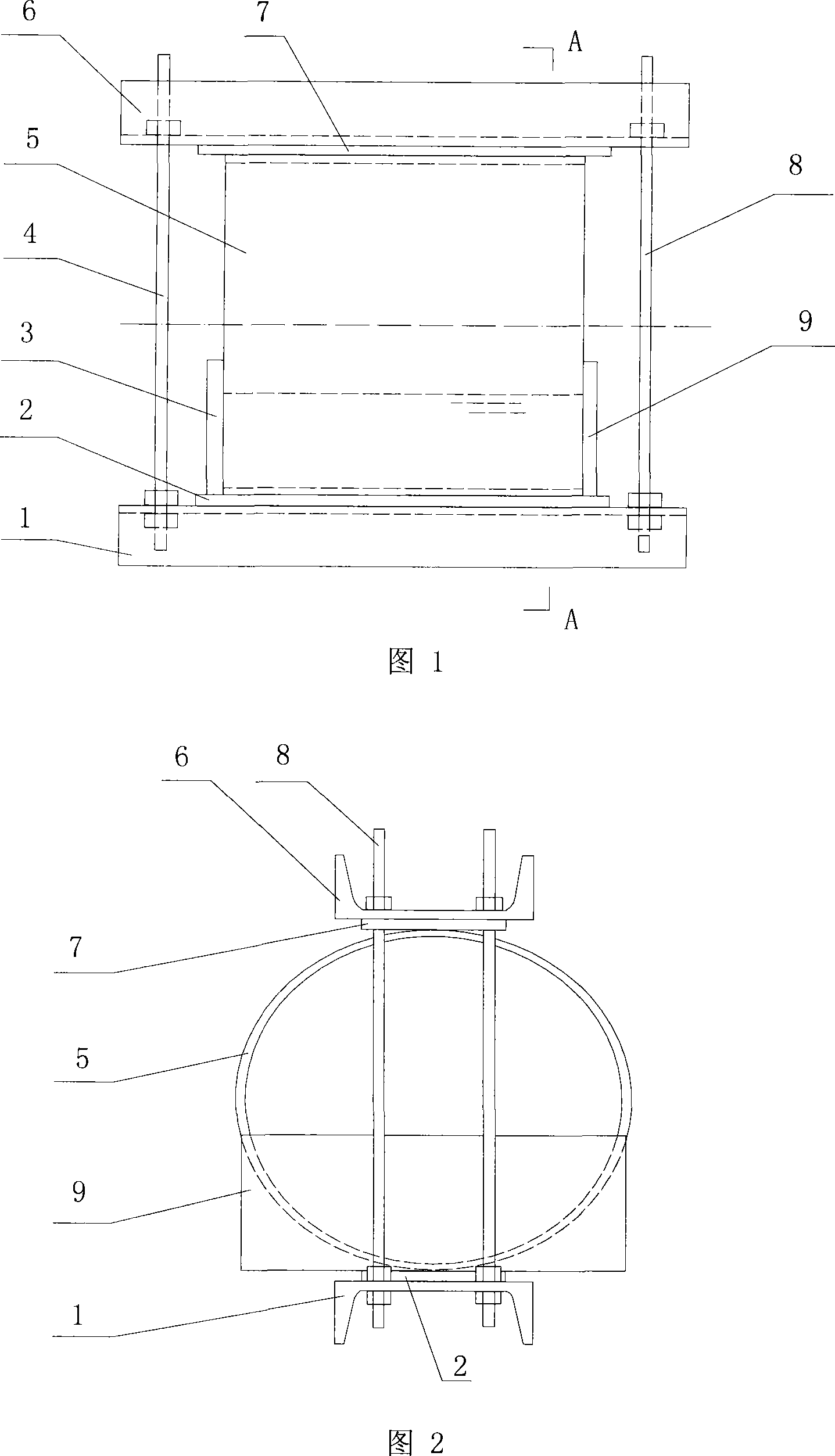
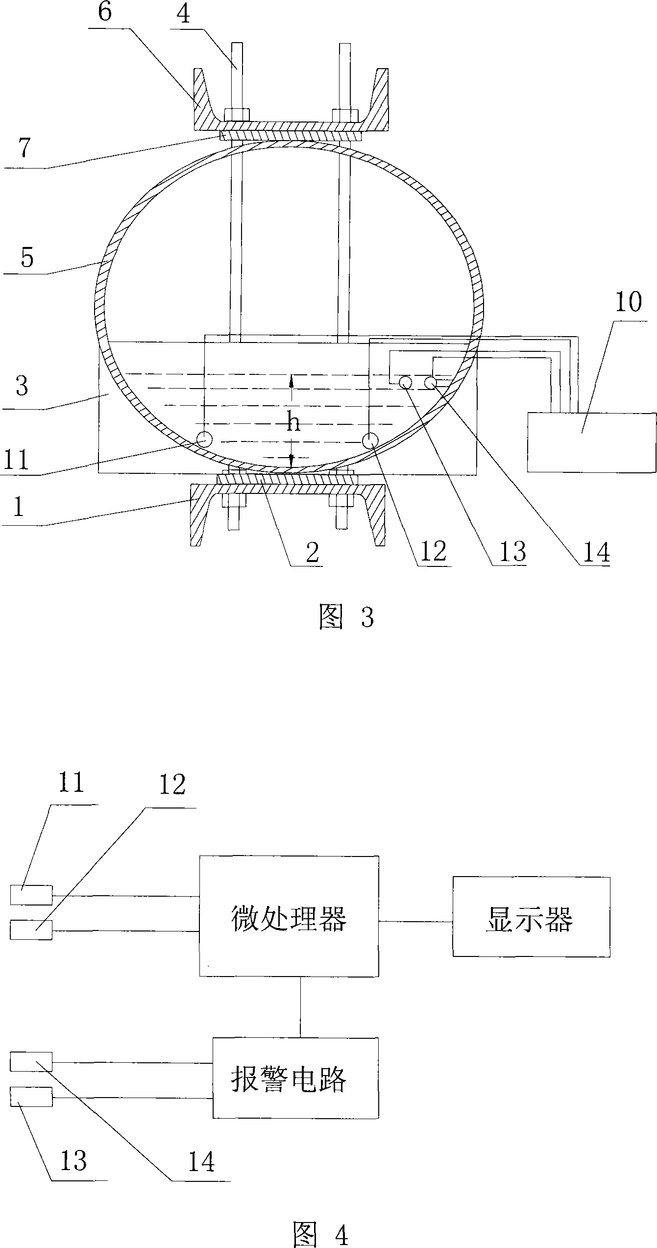
[0026] 1) Preparation of the long-term performance test device for glass steel pipes: as shown in Figure 1, Figure 2, and Figure 3, the long-term performance test device for glass steel pipes consists of a pull-down plate 1, a lower rubber pad 2, a left baffle plate 3, a left pull rod 4, and an upper pull-down plate. Plate 6, upper rubber pad 7, right tie rod 8, right baffle plate 9, and nuts;

[0027] 2) Place the lower rubber pad 2 on the pull-down plate 1, then place the glass steel pipe sample 5 to be tested on the lower rubber pad 2, place an upper rubber pad 7 on the upper end of the glass steel pipe sample 5, and place a rubber pad 7 on the upper rubber pad 7. Pull-up plate 6; the left end of pull-down plate 1 and pull-up plate 6 is fastened by left tie rod 4 and nut, the right end of pull-down plate 1 and pull-up plate 6 is ...


PUM


Abstract

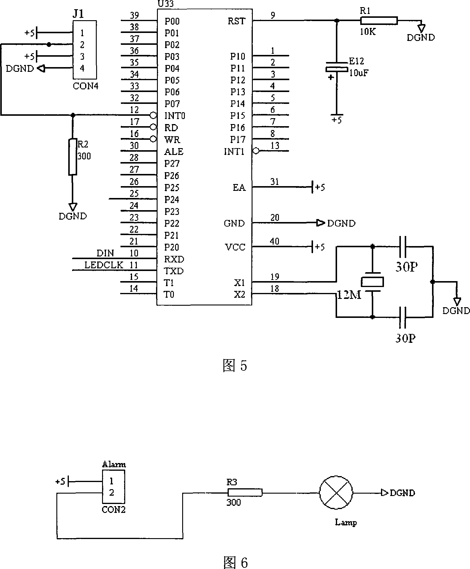
The present invention relates to a test method of a test piece destruction time in a glass-reinforced plastic pipe long-term ring-bending strain test, in particular to a test method of a test piece destruction time in a glass-reinforced plastic pipe long-term performance test. The present invention is characterized in that with the help of the conductive characteristic of corrosive liquor, a corrosion resistant and conductive first interruption electrode 11 and a second interruption electrode 12 are arranged on the two sides of the bottom pipe wall in a glass-reinforced plastic pipe test piece 5; when the glass-reinforced plastic pipe test piece 5 is charged with sulfuric acid corrosive liquor, the first interruption electrode 11 and the second interruption electrode 12 are connected through corrosive liquor, the conductive characteristic of the sulfuric acid corrosive liquor is utilized to make the external interruption pin of a microporocessor in a high level, and the microporocessor starts to record power on time; when the glass-reinforced plastic pipe test piece 5 is broken under the effect of distortion and sulfuric acid corrosion, the sulfuric acid flows out of the glass-reinforced plastic pipe test piece 5 along the fracture, the first interruption electrode 11 and the second interruption electrode 12 are disconnected, the external interruption of the microporocessor is in a low level, and the microporocessor stops timing, thus the test piece destruction time is obtained. The present invention has the advantages of reduced labor intensity, and high accuracy.

Description

technical field [0001] The invention relates to a method for testing the failure time of a sample in a long-term ring bending strain test of a glass steel pipe. Background technique [0002] FRP pipe is a new type of pipe made of glass fiber as reinforcement, resin as matrix, and silica sand as filler. It has the characteristics of corrosion resistance, long service life, high specific strength, light weight, and good hydraulic performance. It is more and more widely used in various projects of water supply and drainage. [0003] According to relevant design standards at home and abroad, the design of FRP pipelines is based on long-term (generally 50 years) performance indicators. Without reliable long-term performance indicators, a more reasonable design cannot be carried out, so a complete set of long-term performance testing methods and equipment is necessary. At present, the long-term performance test of domestic FRP pipes is mainly based on the ASTM D3681 method propo...

Claims


Application Information

Patent Timeline
IPC IPC(8): G01N3/00G01N17/00
Inventor 陈建中李卓球向宏酉
Owner SHENZHEN KANGQIANG CONSTR NEW TECH ENG
Learn More