Device used for measuring distance between moving object and its railway

A technology for moving objects and tracks, applied in measuring devices, using electrical devices, and using electromagnetic/magnetic devices to transmit sensing components, etc., can solve the problems of inconvenient maintenance, high cost, inapplicability, etc. low cost effect

Inactive Publication Date: 2008-01-30
SOUTHWEST JIAOTONG UNIV
View PDF0 Cites 9 Cited by
  • Summary
  • Abstract
  • Description
  • Claims
  • Application Information

AI Technical Summary

Problems solved by technology

[0003] The disadvantages of these two methods are: because the signal transmitter needs to be installed on the ground, when the track is very long, the cost is expensive; and the signal transmitter is active, so it is not easy to maintain when it fails
In addition, when the detection devices designed by these two methods are applied to the situation where the track magnetoresistance or resistance has periodic changes, it will cause periodic changes in the measurement signal, thereby affecting the accuracy of distance detection
Such as the maglev track used in rail transit, the change of its reluctance is periodic, so these two methods are not suitable for the detection of the distance between the maglev vehicle and the track

Method used


Image

  • Device used for measuring distance between moving object and its railway
  • Device used for measuring distance between moving object and its railway
  • Device used for measuring distance between moving object and its railway

Examples


specific Embodiment approach

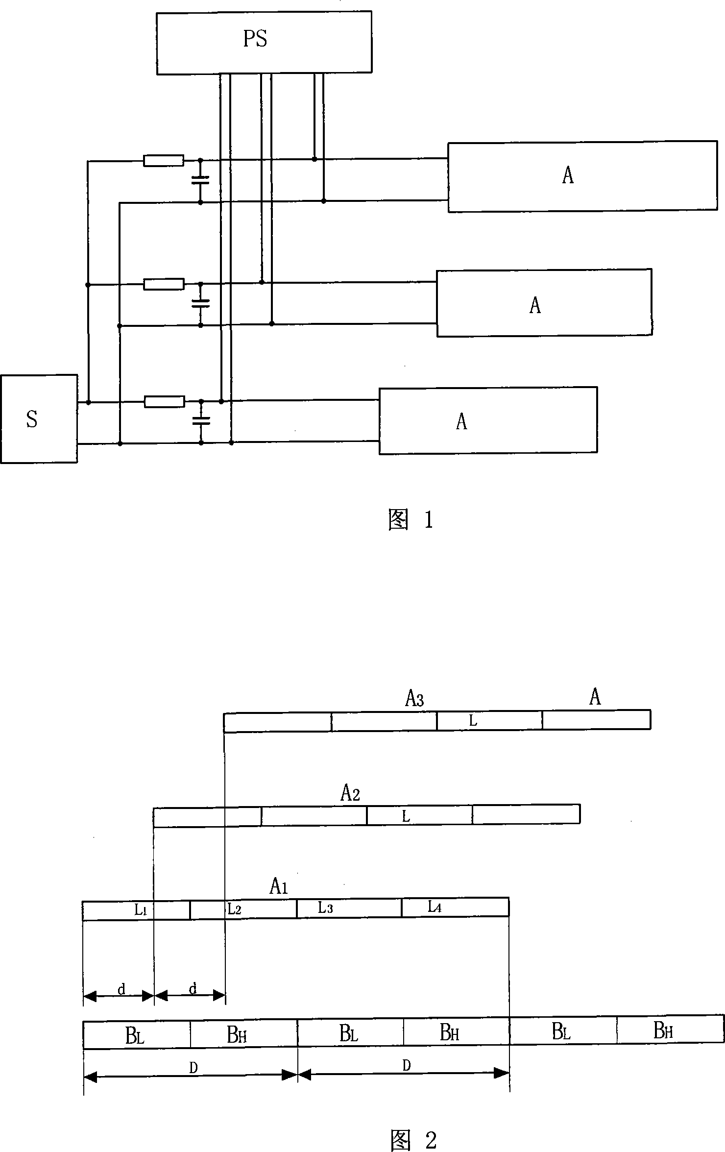
[0022] Figures 1 to 4 show that a specific embodiment of the present invention is: a device for detecting the distance between a moving object and its orbit, including a signal from a high-frequency signal source entering the sensor, and the signal induced by the sensor by a signal processing circuit to process. The high-frequency signal source S, sensor and signal processing circuit PS are all installed on the moving object, and the sensor is composed of induction winding:

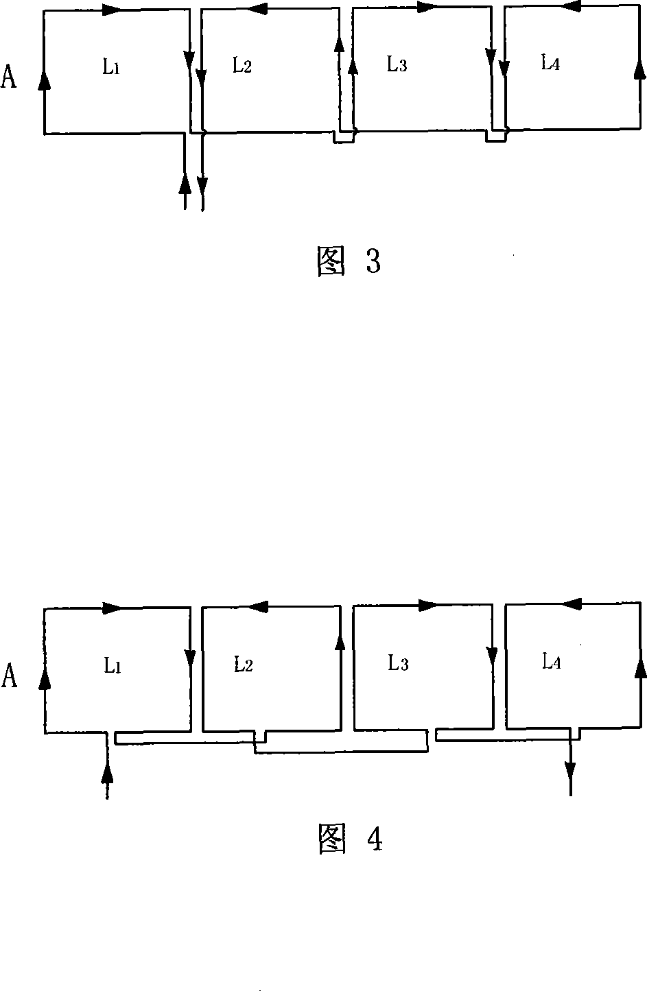
[0023] Each group of induction windings A is composed of four longitudinally arranged induction coils L of the same size wound by a wire, and the winding directions of adjacent induction coils are opposite. The four induction coils are respectively marked as L 1 , L 2 , L 3 , L 4 . The length of the induction winding along the longitudinal direction is equal to twice the longitudinal spacing D of a cycle of the track reluctance or resistance periodic change.

[0024] In this example, the induction wi...

Embodiment 2

[0041] This example is basically the same as the first example, except that the induction winding A is reduced to one group.

Embodiment 3

[0043] This example is basically the same as the first example, except that there are two sets of induction windings A, and one induction coil C for each set. The two sets of windings are staggered along the longitudinal direction of the track, which is half of the period of the track magnetoresistance or resistance length. At any moment during the detection, the magnitude of the change of the high-frequency voltage amplitude generated by the track magnetoresistance or the periodic change of the resistance on the two windings is the same but the direction is opposite.

[0044] The present invention can be used to detect the distance between various objects whose magnetoresistance or resistance changes periodically and the moving objects above them, for example, it can be used to detect the gap between the magnetic levitation vehicle and the magnetic levitation track, so as to ensure the stable suspension and high speed of the magnetic levitation vehicle ,safe operation.


PUM


Abstract

The invention discloses a distance between a moving object and the track detecting device. A high frequency signal source, a transducer and a signal processing circuit of the detecting device are arranged in a moving object. Wherein, the transducer is constituted by an induction winding and the length of the induction winding along the track is equal to or is integer times as much as one longitudinal interval of the periodic variation of the track magnetic resistance or track resistance. The device is suitable for the distance detection between a maglev-vehicle and the track and can not be affected by the track magnetic resistance variation. The device has the advantages of high detection accuracy, all components of the device being arranged on the moving object, less quantity of components, low cost and easy maintenance.

Description

technical field [0001] The invention relates to a device for detecting the distance between a moving object and its track, in particular to a device for detecting the distance between a maglev vehicle and its track. Background technique [0002] There are generally two methods for detecting the distance between a moving object and the track: the first is to lay a certain shape of electrical signal transmitter along the track, and install a receiver on the vehicle. The electrical signal received by the receiver is inversely proportional to the distance Attenuation trend, which can detect the distance between the floating moving object and the orbit; the second method is that the moving object receiver detects the phase offset (delay component) of the pulse signal or M-sequence signal sent by the orbit transmitter distance. [0003] The disadvantages of these two methods are: due to the need to install the signal transmitter on the ground, when the track is very long, the cos...

Claims


Application Information

Patent Timeline
IPC IPC(8): G01B7/14G01D5/12
Inventor 张昆仑王滢李熹董金文刘国清靖永志郭育华王莉郭小舟
Owner SOUTHWEST JIAOTONG UNIV
Why Eureka
Try Eureka