Cast-in-situ concrete hollow slab

A technology of cast-in-place concrete and hollow slabs, which is applied in the direction of floor slabs, building components, buildings, etc., and can solve the problems of difficult pouring and compacting of cast-in-place concrete, and difficulty in compacting and forming, and achieves convenient application and implementation, easy pouring and compacting, and accurate position Effect

Inactive Publication Date: 2008-01-30
湖南邱则有专利战略策划有限公司
View PDF1 Cites 0 Cited by
  • Summary
  • Abstract
  • Description
  • Claims
  • Application Information

AI Technical Summary

Problems solved by technology

This formwork member has the characteristics of high strength, simple structure, and convenient construction and transportation. However, when the formwork member is applied to the construction process of the cast-in-place concrete hollow floor, it is difficult to pour and tamp the cast-in-place concrete under the lower bottom of the formwork member. It is difficult to form compactly, especially when the size of the formwork components is large, the performance is more obvious. Therefore, it is urgent to develop a new type of cast-in-place concrete hollow slab.

Method used


Image

  • Cast-in-situ concrete hollow slab
  • Cast-in-situ concrete hollow slab
  • Cast-in-situ concrete hollow slab

Examples


Embodiment Construction

[0054] The present invention will be further described below in conjunction with the accompanying drawings and embodiments.

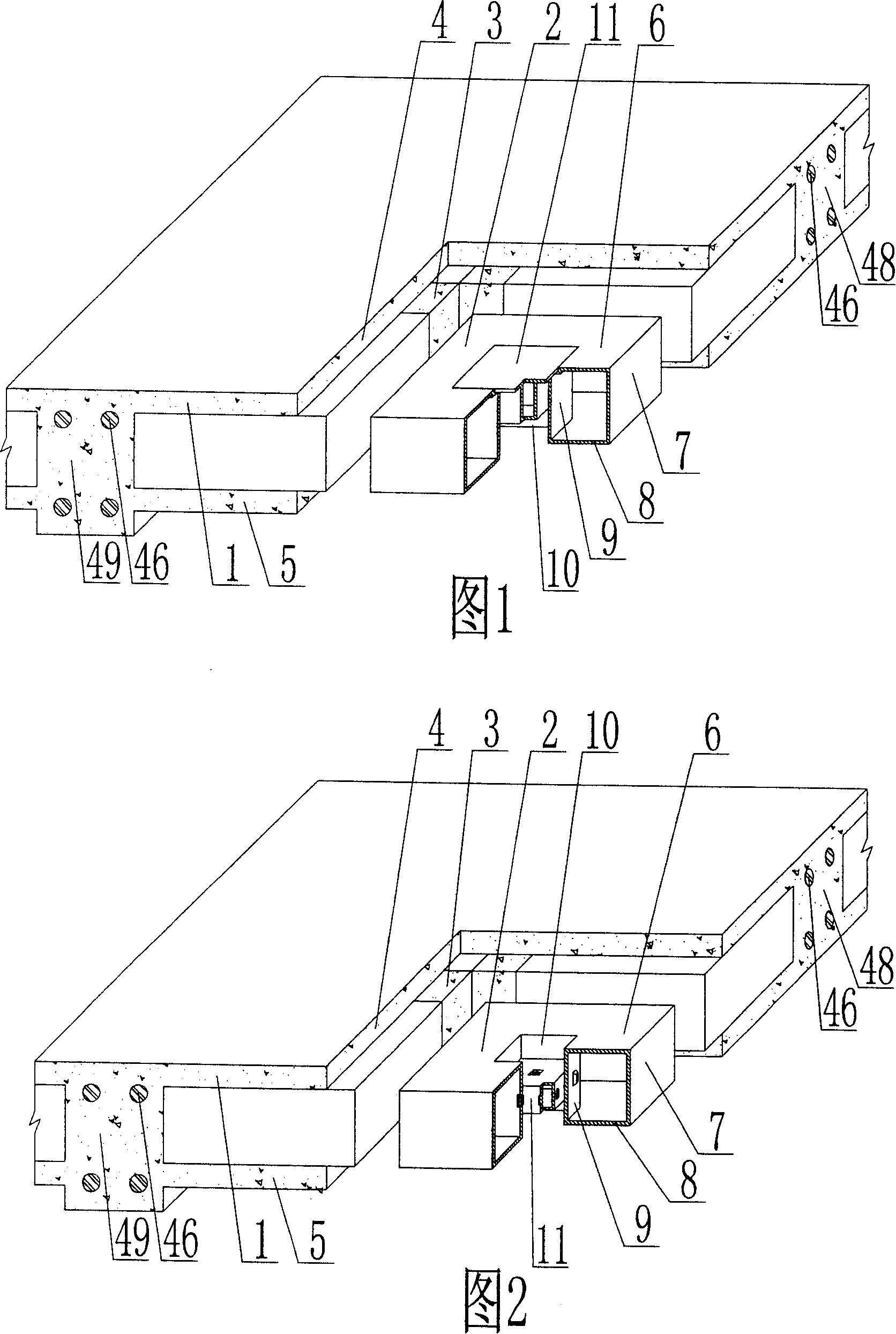
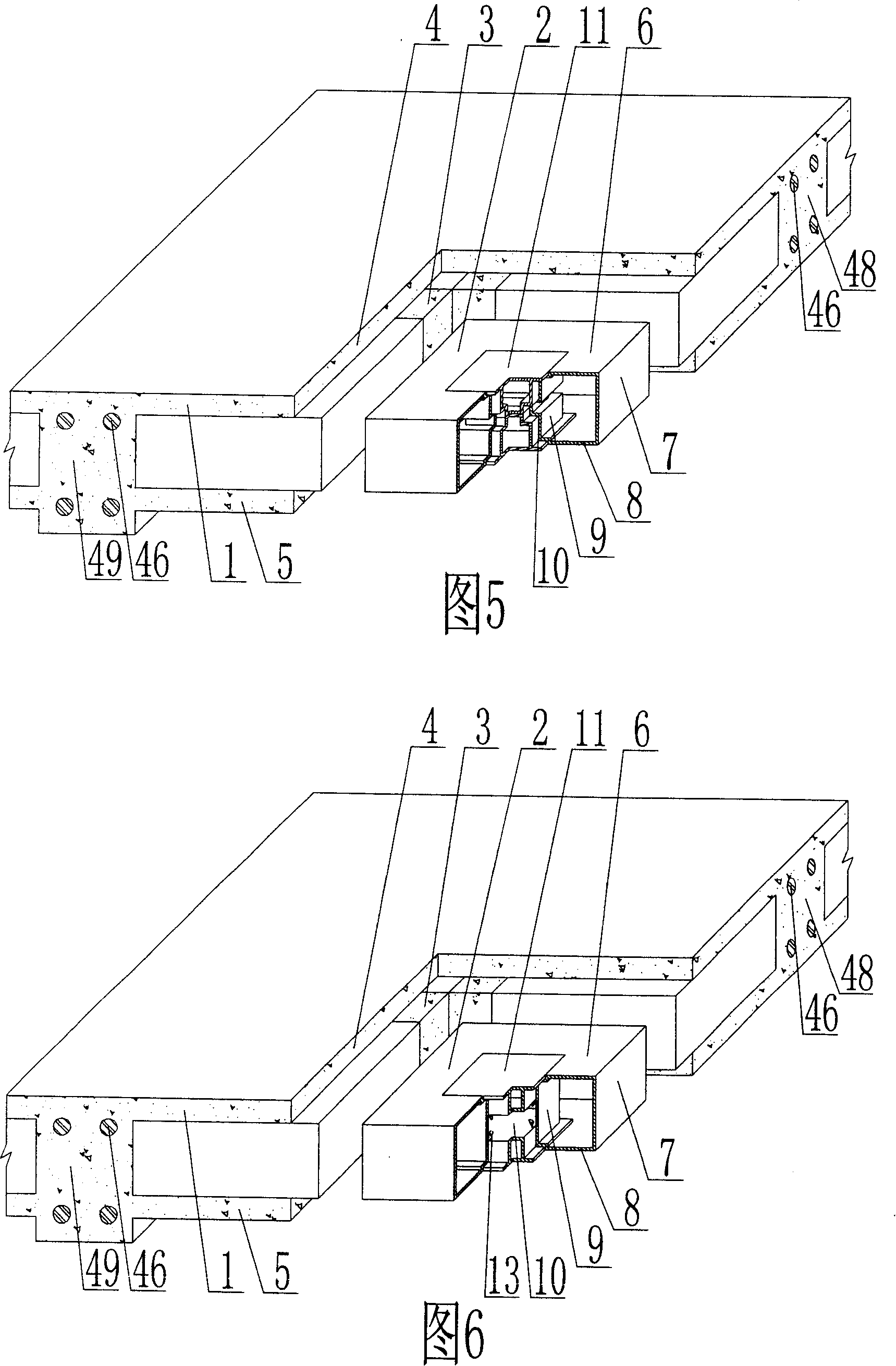
[0055] As shown in the accompanying drawings, the present invention includes a reinforced concrete 1 and a lightweight carcass 2, the lightweight carcass 2 is wrapped in the reinforced concrete 1, the lightweight carcass 2 are arranged alternately, and there are cast-in-place reinforced concrete ribs 3 between them , above which is the cast-in-place reinforced concrete upper plate 4, under which is the cast-in-place reinforced concrete lower plate 5, the lightweight carcass 2 includes an upper shell 6, surrounding side shells 7, lower shell 8, upper shell 6, surrounding side shells 7 , The lower shell 8 forms a closed cavity, which is characterized in that it also includes a through-hole pipe 9, and the through-hole pipe 9 is arranged in the closed cavity of the lightweight carcass 2, and at least one of the light-weight carcass 2 is formed by a through ...


PUM


Abstract

The invention relates to a cast-in-place concrete hollow core slab, comprising a reinforced concrete (1) and light matrixes (2) which are enwrapped in the reinforced concrete (1) and arranged interphasely and between which is provided with cast-in-place reinforced concrete ribs (3). The invention is characterized in that the invention further comprises a via pipe (9) that is arranged in the closed cavity of the light matrix (2); the light matrix (2) is provided with at least one hole (10) for concrete in situ pouring formed by via of the via pipe (12), which goes through the upper and the lower shell surface of the light matrix (2) and the hole (10) is provided with a son tyre die (11) that blocks the upper opening of the hole. The invention is applicable to various hollow core slabs, hollow floors, roofs, foundation slabs, walls and fasting bridges of cast-in-place or prestressed reinforced concrete, and especially applicable to hollow girderless floors.

Description

(1) Technical field [0001] The invention relates to a cast-in-place concrete hollow slab. (2) Background technology [0002] At present, the cast-in-place concrete hollow floor is a widely used floor structure. The lightweight permanent tire molds filled in it include various hollow tubes and boxes, and the boxes are hollow or solid. For example, the patent No. ZL99249798.1, which the applicant applied for on November 29, 1999, is a utility model patent named "fiber-reinforced thin-walled member for reinforced concrete filling", which discloses a thin-walled formwork member, including an upper plate, The surrounding side walls, the lower bottom, the upper plate, the surrounding side walls, and the lower bottom form a polyhedral cavity, and the upper plate, the surrounding side walls, and the lower bottom contain fiber reinforcements. This formwork member has the characteristics of high strength, simple structure, and convenient construction and transportation. However, when...

Claims


Application Information

Patent Timeline
IPC IPC(8): E04B5/18E04B5/23E04B5/36E04B5/16E04B1/16E04C1/00
Inventor 邱则有
Owner 湖南邱则有专利战略策划有限公司
Why Eureka
Try Eureka