
Pressure control valve having intrinsic feedback system

A pressure regulation and feedback system technology, applied in fluid pressure actuating devices, servo motor components, mechanical equipment, etc., can solve problems such as large energy loss, poor impedance, and inability to run stably

Inactive Publication Date: 2008-01-23
RAYTHEON SARCOS LLC
View PDF0 Cites 4 Cited by
  • Summary
  • Abstract
  • Description
  • Claims
  • Application Information

AI Technical Summary

Problems solved by technology

Due to the above problems, these valves and systems cannot operate stably over a large bandwidth
Also, when not all valves in a multi-valve system are in use, significant energy can be lost
Finally, these systems exhibit poor resistive

Method used


Image

  • Pressure control valve having intrinsic feedback system
  • Pressure control valve having intrinsic feedback system
  • Pressure control valve having intrinsic feedback system

Examples


Embodiment Construction

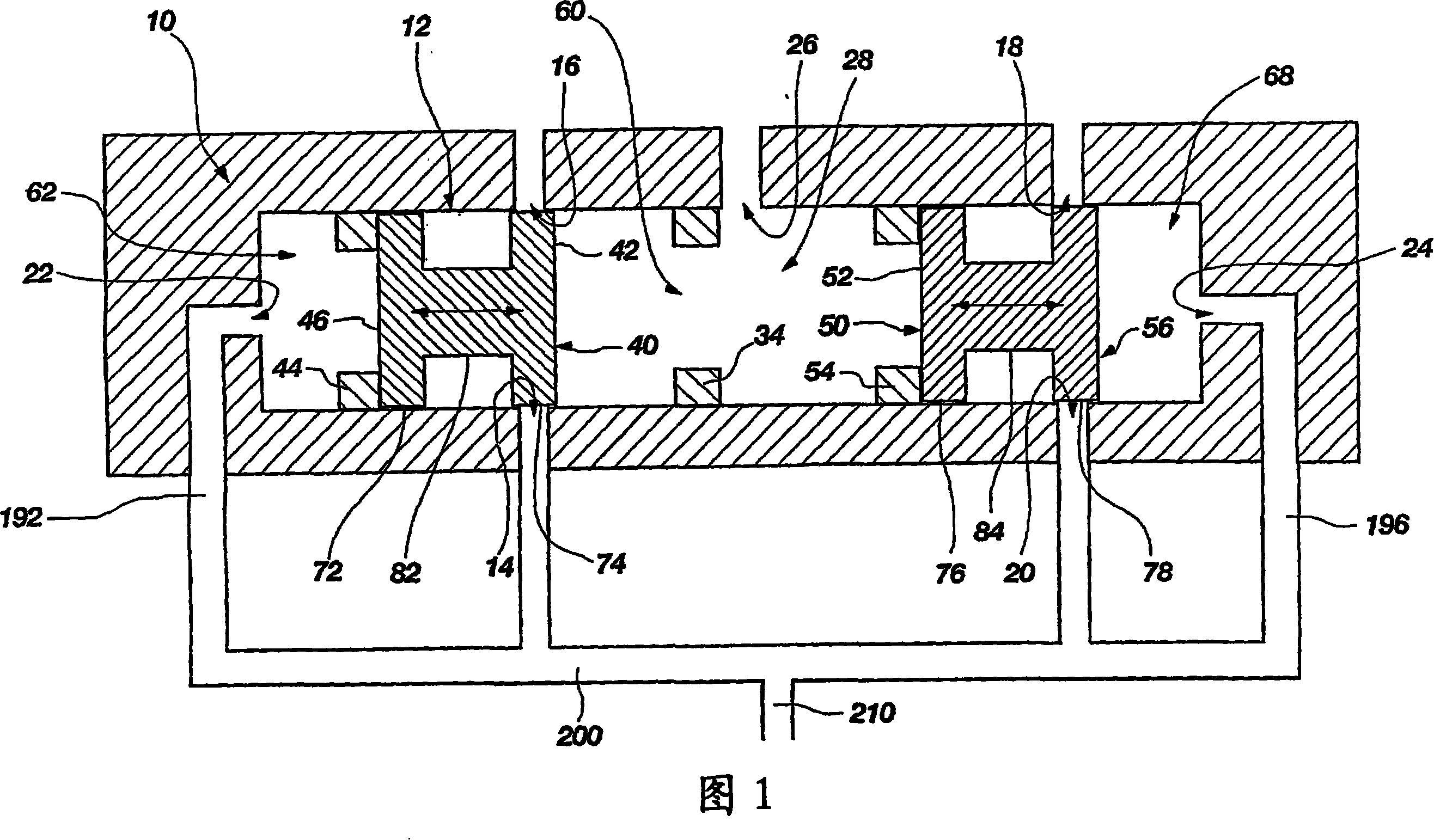
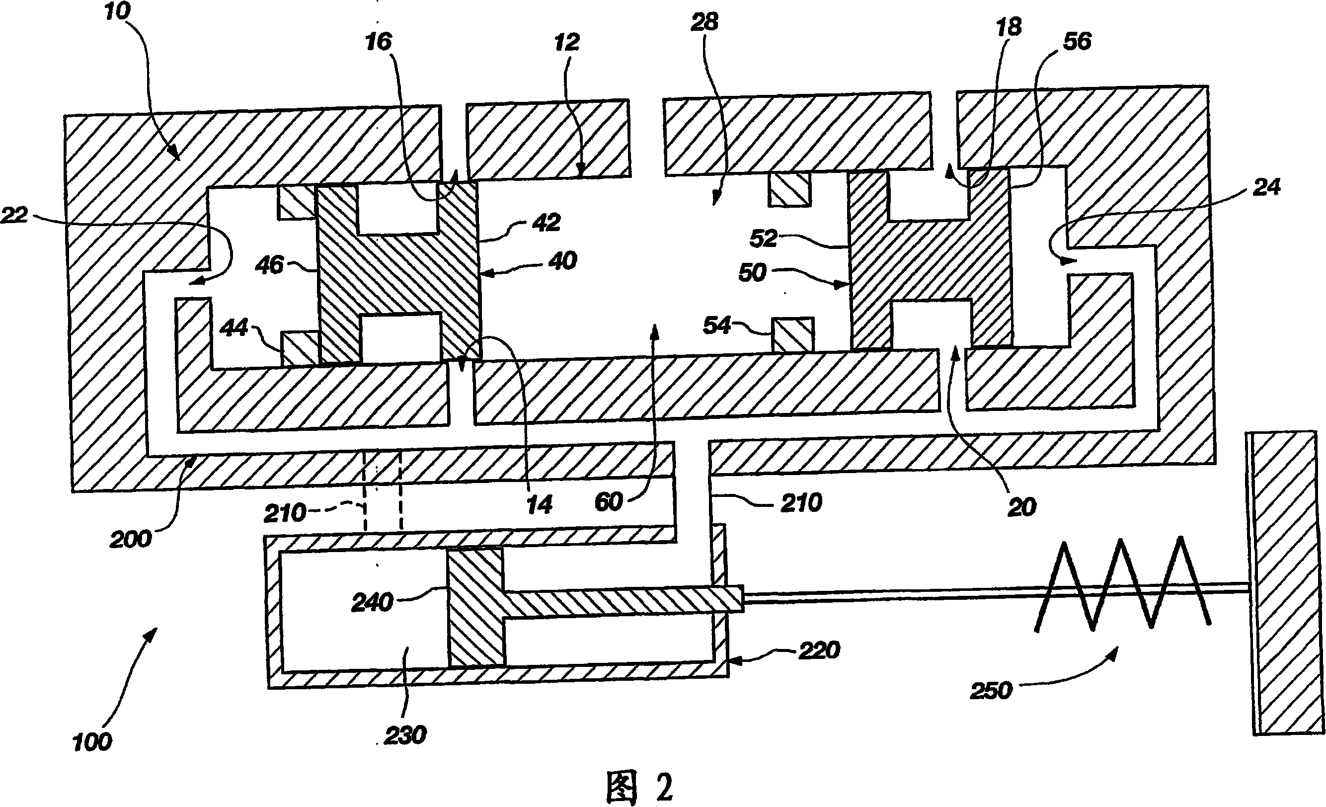
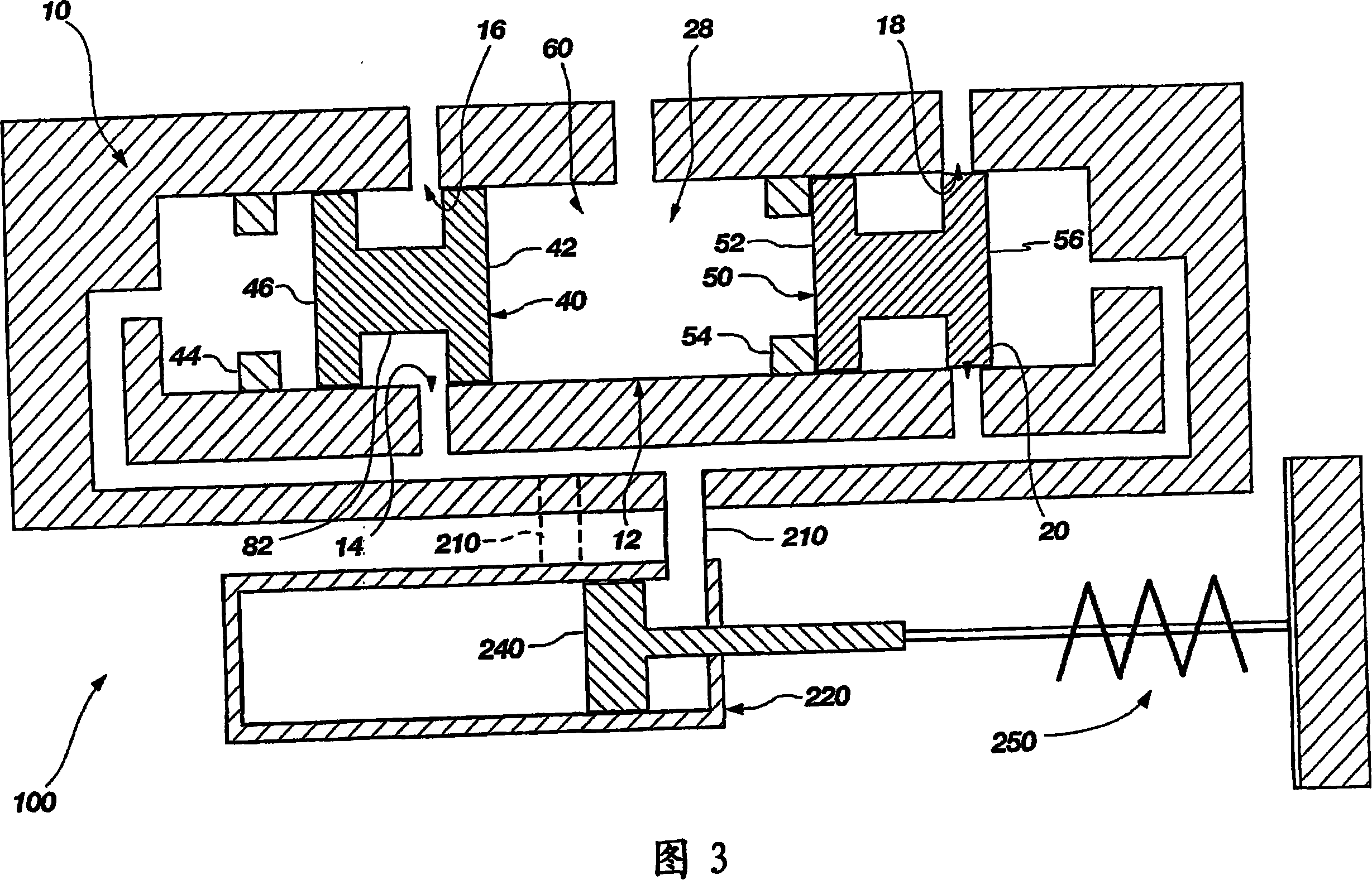
[0031] The following detailed description of exemplary embodiments of the invention refers to the accompanying drawings, which form a part hereof, and in which are shown by way of illustrations several exemplary embodiments in which the invention may be practiced. Although these exemplary embodiments have been described in sufficient detail to enable those skilled in the art to practice the invention, it should be understood that other embodiments may be implemented and the invention may be modified in various ways without departing from the spirit and scope of the invention. Therefore, the following more detailed description of the embodiments of the present invention—as shown in FIGS. The features and characteristics of the invention are described, the best mode of the invention is suggested, and sufficient to enable one skilled in the art to practice the invention. Accordingly, the scope of the invention is defined solely by the appended claims.

[0032] The following deta...


PUM


Abstract

The present invention generally describes a method and system for controlling the motion of an actuatable load acting or operating within a servo or servo-type system, wherein the motion of the load is achieved by means of uniquely configured to provide inherently pressure regulated The pressure regulating valve (10) is controlled. Because of its performance, the pressure regulating valve (10), which can be called a dynamic pressure regulator, uses dual spools (40) and (50) that are physically independent of each other and freely supported in the valve body (12) to regulate the overall system. The pressure between the control or pilot pressure and the load or load pressure. Although physically independent of each other, the dual spools (40) and (50) of the pressure regulating valve (10) cooperate to maintain a state of equilibrium in the system, that is, to remain acting on the actuator (220) or The pressure inside the actuator (load pressure) or the feedback pressure corresponding to the load pressure is the same as the control or pilot pressure. Furthermore, due to the construction and function of the dual spools (40) and (50) and the feedback system acting on the spools (40) and (50), pressure regulation and control are inherent to the pressure regulating valve (10), whereby Eliminates the need for electronic or mechanical user control systems.

Description

technical field [0001] The present invention relates to servo valves or servo-type valves configured to control or regulate the flow and / or pressure of fluid within a servo system or other control system, and more particularly to pressure regulating valves with an inherent feedback system, wherein the pressure regulating valve is configured to There are dual independent spool valves operating to regulate the flow and especially the pressure of fluid within an open loop or closed loop system, especially between a control or pilot pressure source and a load pressure source. Background technique [0002] Control and servo systems such as hydraulic or pneumatic systems are well known and operate on the simple principle of transferring pressure from an application location to an output location via an incompressible fluid. This transfer is usually accomplished by a cylinder containing a piston that pushes the incompressible fluid through a fluid line into another cylinder at a di...

Claims


Application Information

Patent Timeline
IPC IPC(8): F15B15/02F15B15/08F15B13/04
Inventor S·C·雅各布森S·奥尔森M·莫里森
Owner RAYTHEON SARCOS LLC
Learn More