
Oil extraction indicator and using method thereof

A technology of dynamometer and dynamometer chart, which is applied in the direction of mining fluid, earthwork drilling, measurement, etc., can solve the problems of messy, undiscovered, and inability to analyze dynamometer charts, etc., so as to increase effectiveness and reduce Requirements, the effect of reducing the loss of production stoppage

Inactive Publication Date: 2008-01-16
刘克文
View PDF1 Cites 7 Cited by
  • Summary
  • Abstract
  • Description
  • Claims
  • Application Information

AI Technical Summary

Problems solved by technology

[0011] 6. We might as well go back and consider: the display screen is not replaced with a color display screen, it is still a black and white display screen, so many dynamometer diagrams are overlapped and intertwined, making a mess, and it is impossible to distinguish which curve belongs to which dynamometer diagram Yes, obviously, in this case, the analysis of the dynamometer diagram cannot be done
[0022] At present, after inquiry, no relevant reports have been found on the measurement of the above-mentioned "regression dynamometer diagram", "color dynamometer diagram", "dynamic dynamometer diagram" and "change curve of characteristic points of dynamometer diagram"

Method used


Image

  • Oil extraction indicator and using method thereof

Examples


Embodiment 1

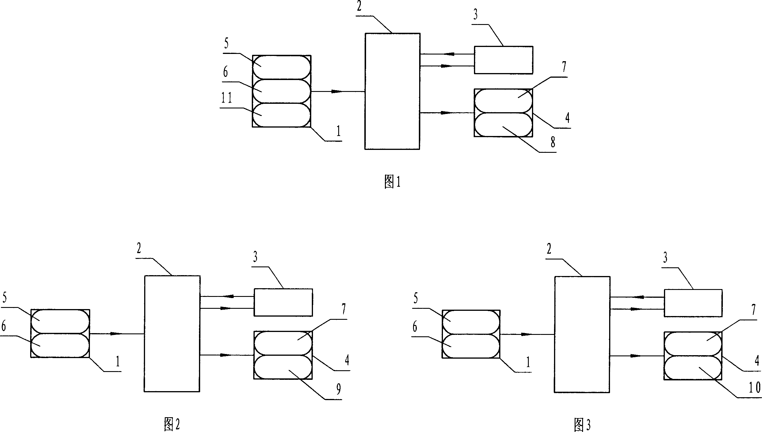
[0073] Embodiment 1, embodiment 2, embodiment 3 as shown in Fig. 1, Fig. 2, Fig. 3, by input device 1 (selection comprises, data key-in device 5, display power acquisition processing unit 6, peripheral sensor unit 11), central It consists of processor 2, storage device 3 and display device 4.

[0074] The calculation program is stored in the "storage device 3".

[0075] Its working process is that the parameters obtained by the input device 1 are transmitted to the central processing unit 2, and the central processing unit 2 processes the data to obtain a variety of curves and graphics and other data, including ground dynamometer diagrams and pump dynamometer diagrams. , regression dynamometer diagram, etc., are transmitted to the storage device 3 for storage, and during analysis, a single curve graph, multiple static curve graphs, dynamic curve graphs, etc. are selected to be displayed on the color display screen of the display device 4 according to the set color .

[0076]...


PUM


Abstract

The invention discloses a color dynamometer for oil extraction and application method thereof. The color power indicator for oil extraction relates to a device for measuring and monitoring curves, figures and related data reflecting operating state of pumping well, in particular to a device for measuring and monitoring various dynamometer diagrams and related data reflecting operating state of oil well pump, and its display device is directly or indirectly provided with a color display screen. During application, the device continuously measures dynamometer diagrams and then stores corresponding data. When analyzing, the device transmits a plurality of curves and figures that is needed to be compared and has been stored in the device, in the form of single curve and figure, multiplex static curves and figures and dynamic curves and figures, to the color display screen for displaying. The invention provides a powerful novel mean for diagnosis of oil well pump, thereby remarkably improving the accuracy and effectiveness of the diagnosis, and is important for failure prediction of oil well pump.

Description

technical field [0001] The present invention relates to: 1. An instrument for measuring and monitoring curves and graphs reflecting the working state of pumping wells and related data, in particular, an instrument for measuring and monitoring various dynamometer diagrams and related data reflecting the working state of oil pumps; 2. A method for using an oil production dynamometer. technical background [0002] Patent No. CN87205901 "Digital Dynamometer for Pumping Wells" discloses an intelligent instrument for measuring the dynamometer diagram. It submits the collected suspension point load parameters and polished rod displacement parameters to the microcomputer system for calculation and processing, and obtains Surface dynamometer diagram and downhole (pump) dynamometer diagram at any depth. [0003] The CN872051 patent forms a monochromatic dynamometer diagram. [0004] Although the monochrome dynamometer is easy to operate and the hardware configuration is relatively s...

Claims


Application Information

Patent Timeline
Patent Type & Authority Applications(China)
IPC IPC(8): E21B47/00E21B43/00E21B47/008
Inventor 刘克文
Owner 刘克文
Learn More