
Oscillator, negative resistance circuit and its oscillating method

An oscillator and negative resistance technology, applied in the field of oscillators, can solve problems such as the failure of voltage-controlled oscillators to work normally

Inactive Publication Date: 2008-01-09
MEDIATEK INC
View PDF0 Cites 14 Cited by
  • Summary
  • Abstract
  • Description
  • Claims
  • Application Information

AI Technical Summary

Problems solved by technology

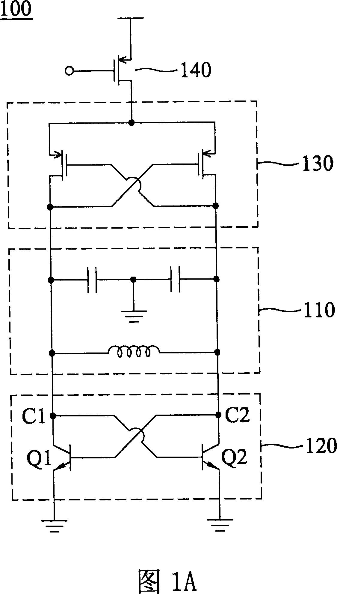
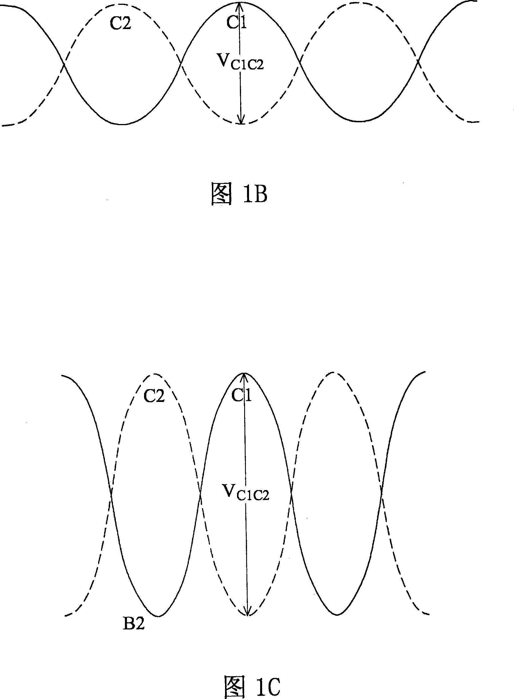
For example, when the V B2C2 =0.5V, the bipolar junction transistor Q2 will enter a saturated state, and when any bipolar junction transistor enters a saturated state, the voltage-controlled oscillator cannot work normally

Method used


Image

  • Oscillator, negative resistance circuit and its oscillating method
  • Oscillator, negative resistance circuit and its oscillating method
  • Oscillator, negative resistance circuit and its oscillating method

Examples


Embodiment Construction

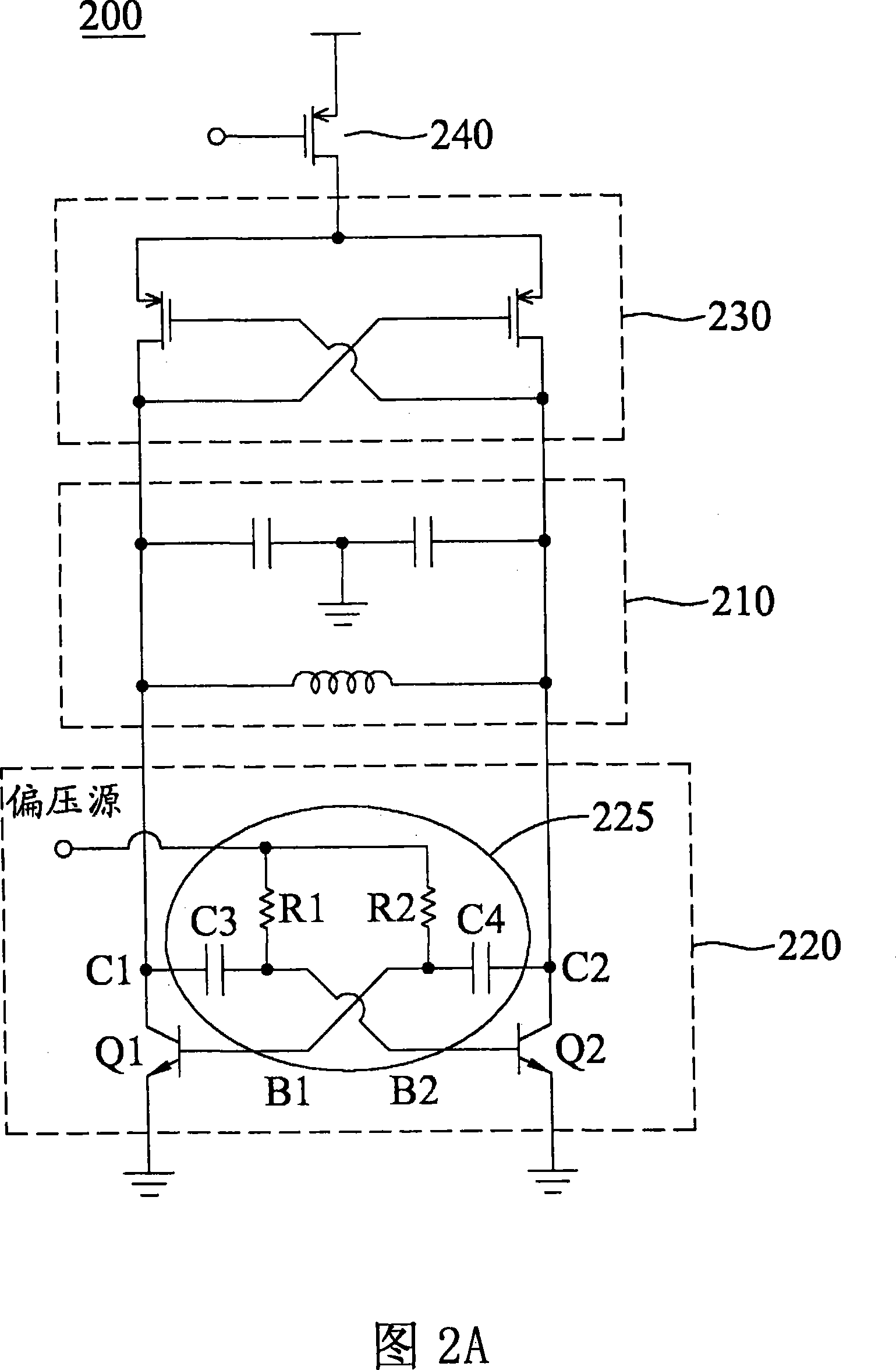
[0022] FIG. 3A is a circuit diagram of a VCO including a voltage drop generator according to an embodiment of the present invention. The VCO 300 includes an LC tank 310 , negative resistance circuits 320 and 330 and a current source 340 . The negative resistance circuits 320 and 330 respectively include cross-coupled NPN bipolar junction transistors and metal oxide semiconductor transistors. The collectors C3 and C4 of the NPN bipolar junction transistors Q3 and Q4 of the negative resistance circuit 320 are coupled to the LC tank 310 , and the drains of the MOS transistors of the negative resistance circuit 330 are also coupled to the LC tank 310 . In FIG. 3A , the emitter of the NPN BJT is grounded and the source of the MOS transistor is coupled to a supply voltage through a current source 340 . It should be noted that the emitter of the NPN bipolar junction transistor may not be grounded, and the source of the metal oxide semiconductor transistor may not be coupled to the ...


PUM


Abstract

An oscillator, comprising an LC tank circuit and a negative resistance circuit. The negative resistance circuit is coupled to the LC tank circuit and comprises a pair of transistors and a pair of voltage drop generators. The transistors have first terminals and second terminals, wherein the first terminals are cross-coupled to the second terminals thereof. The voltage drop generators are respectively coupled between the first and second terminals of the transistors.

Description

technical field [0001] The present invention relates to an oscillator, and more particularly to an oscillator including a voltage drop generator which improves its output swing, a negative resistance circuit and an oscillating method thereof. Background technique [0002] FIG. 1A is a circuit diagram of a basic voltage controlled oscillator (VCO) 100 , which includes an LC tank 110 , negative resistance circuits 120 and 130 and a current source 140 . The negative resistance circuits 120 and 130 respectively include cross coupled bipolar junction transistors (BJT) and metal-oxide-semiconductor (MOS) transistors. The collectors C1 and C2 of the BJTs Q1 and Q2 of the negative resistance circuit 120 are coupled to the LC tank 110 , and the drains of the MOS transistors of the negative resistance circuit 130 are also coupled to the LC tank 110 . The emitter of the BJT is grounded, and the source of the MOS transistor is coupled to the current source 140 . [0003] Figure 1B and...

Claims


Application Information

Patent Timeline
IPC IPC(8): H03B5/20
Inventor 傅家煌
Owner MEDIATEK INC
Learn More