
Tyre module and tyre comprising a module of this type

A tire module, pneumatic tire technology, applied in tire measurement, tire parts, electrical components and other directions, can solve problems such as complex structure

Inactive Publication Date: 2008-01-02
CONTINENTAL TEVES AG & CO OHG
View PDF2 Cites 21 Cited by
  • Summary
  • Abstract
  • Description
  • Claims
  • Application Information

AI Technical Summary

Problems solved by technology

This structure with the bar spring and the clip spring arranged at the free end of the bar spring is very complicated

Method used


Image

  • Tyre module and tyre comprising a module of this type
  • Tyre module and tyre comprising a module of this type

Examples


Embodiment Construction

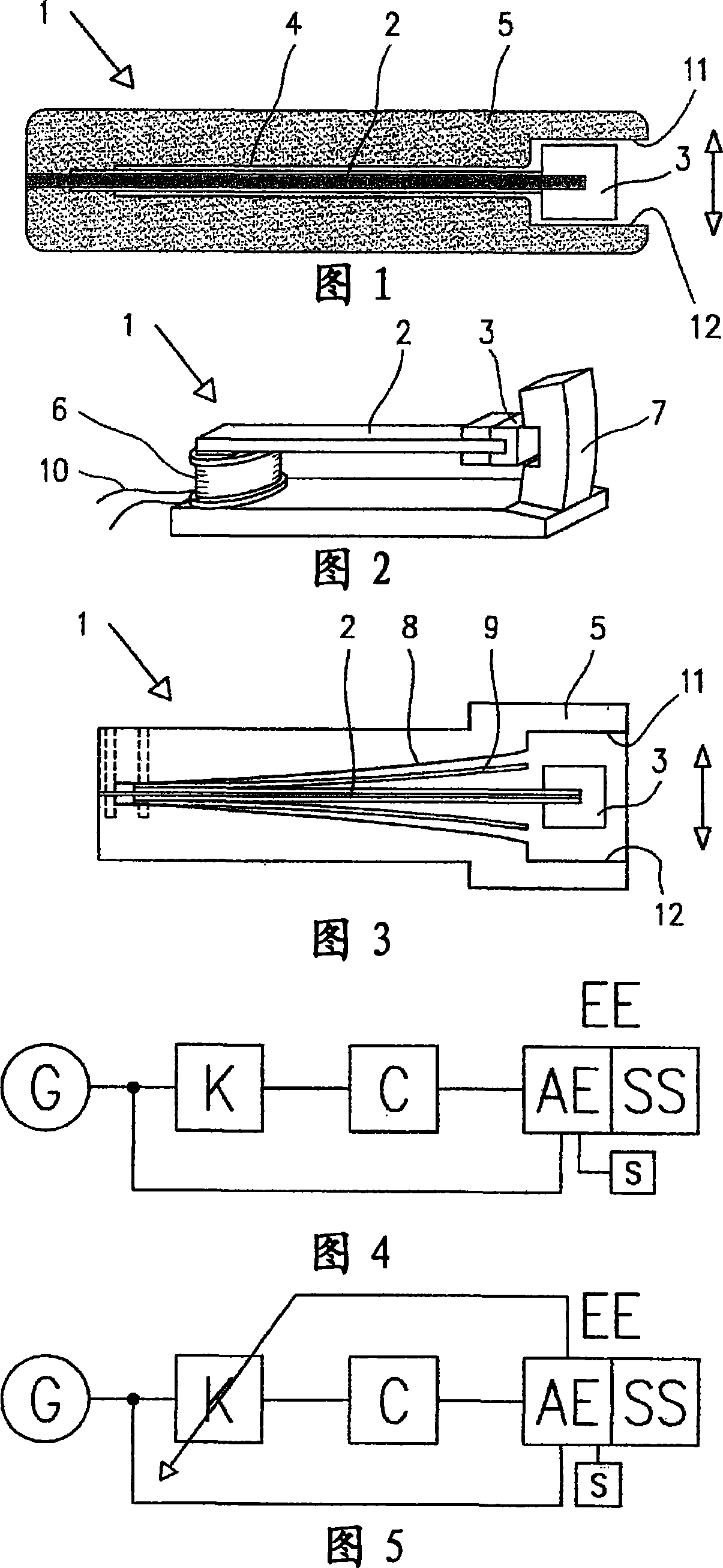
[0027] FIG. 1 shows a section through a tire module 1 which is preferably arranged on the inner side of a pneumatic tire opposite the tread region. The housing part 5 has a groove in which the spring part 2 , which is a leaf spring in the present embodiment, is clamped at one end. At the end of the spring element 2 opposite the clamping end there is a vibrating mass 3 which vibrates as a result of mechanical impulses. The spring part 2 and the seismic mass 3 together form a spring-mass oscillator which moves oscillatingly within the housing 5 . A piezoelectric layer 4 is provided on the top and bottom of the spring element 2, said layer being suitably polarized and equipped with a contact surface. The application is designed such that a deflection of the spring element 2 results in an elongation or compression of the piezoelectric layer 4 . A voltage can be taken from contact surfaces not shown, so that the kinetic energy caused by the oscillating seismic mass 3 can be conve...


PUM

PropertyMeasurementUnit
Lengthaaaaaaaaaa

Abstract

The invention relates to a tyre module for recording tyre condition variables, comprising a spring element (2) that is fixed on one side and a conversion unit (2, 3, 4, 6, 7), in which the displacement energy is converted into electric energy. The spring element (2) is configured as a rod spring, torsion spring or leaf spring and carries a seismic mass (3) on its free end. The spring element transmits acceleration steps of the seismic mass (3) to the conversion unit (2, 3, 4, 6, 7).

Description

technical field [0001] The invention relates to a tire module for measuring tire state quantities and to a pneumatic tire with such a tire module, which has a spring element compressed at one end and a conversion unit in which kinetic energy is converted into electrical energy. [0002] The invention is particularly suitable for determining the state quantity and performance of highway pavement with energy autonomous system. Background technique [0003] A system for determining operating parameters of vehicle tires is known from DE 4402136 A1, in which a sensor unit, an electronic processing unit and piezoelectric elements for supplying energy to other elements of the system are arranged on a support. The piezoelectric element has a multilayer structure. [0004] Furthermore, a device for supplying energy to sensors is known from DE 10103952 A1, which has an active piezoelectric transducer which can be deformed by a mechanical energy store and provides a corresponding vol...

Claims


Application Information

Patent Timeline
IPC IPC(8): B60C23/04
CPCB60C23/0411H02K35/02H01L41/1136B60C23/041H10N30/306B60C23/04B60C23/02
Inventor H·贝伦兹C·赖曼T·科施尼茨基
Owner CONTINENTAL TEVES AG & CO OHG
Learn More