Musical instrument system
A technology for musical instruments and ontology, applied in musical instruments, electroacoustic musical instruments, supports of musical instruments, etc., can solve problems such as difficulty in connecting, fixing and positioning, etc.
- Summary
- Abstract
- Description
- Claims
- Application Information
AI Technical Summary
Problems solved by technology
Method used
Image
Examples
no. 1 Embodiment approach
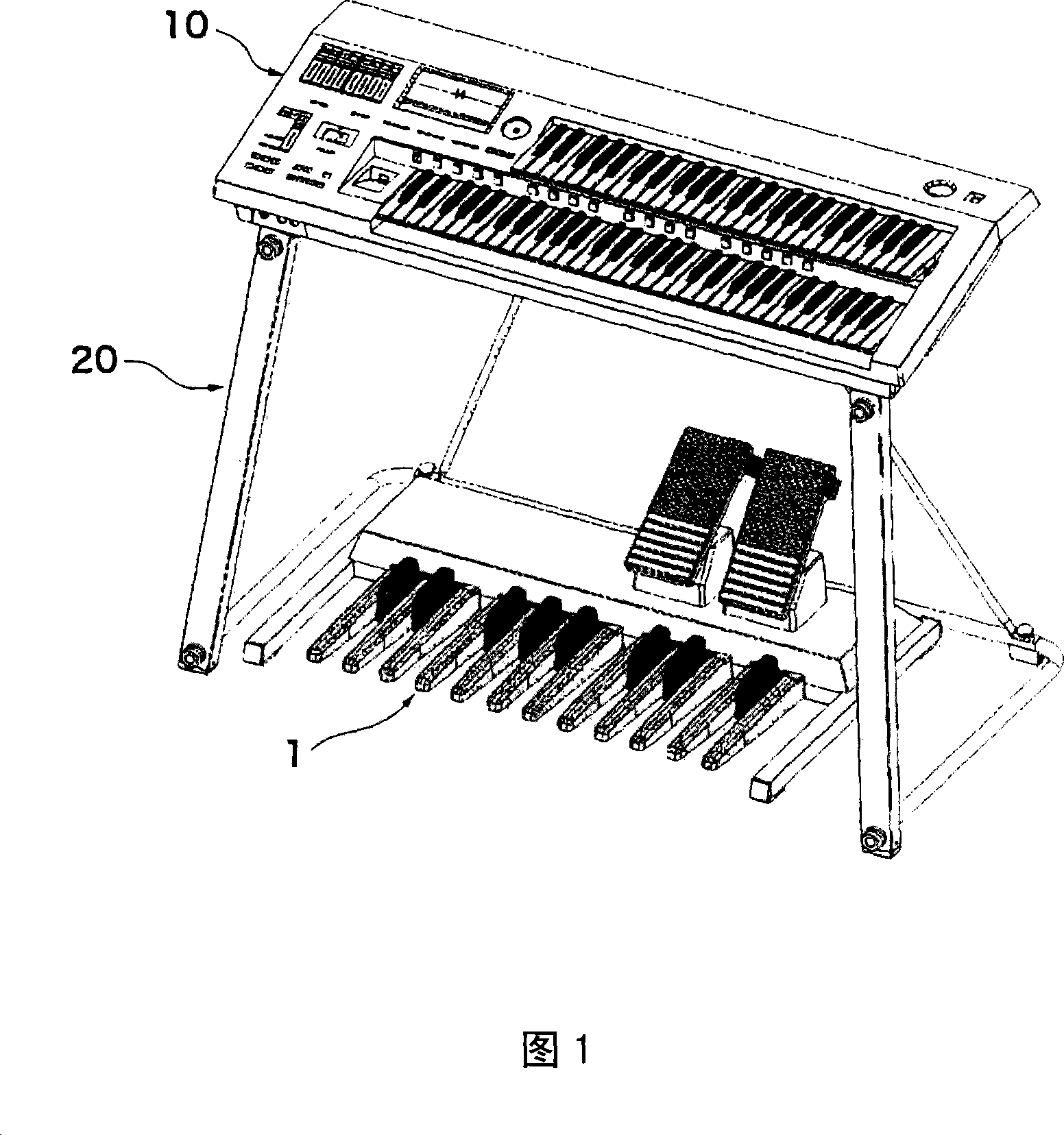
[0031] figure 1 It is a perspective view of the musical instrument system according to the first embodiment of the present invention. This musical instrument system is configured such that a musical instrument body 10 is supported by a stand 20 and further includes a pedalboard 1 . Pedalboard 1 rests on the flat ground inside support 20 . The musical instrument body 10 is constituted as an electronic keyboard instrument having two layers of keyboard parts. The pedalboard 1 is electrically connected to the instrument body 10 , but the diagram showing the wiring thereof is omitted here. Hereinafter, the front-rear direction and the left-right direction are referred to based on the player. Therefore, with respect to the musical instrument body 10, the player's side is the front side, and the arrangement direction of the keyboards is the left-right direction.
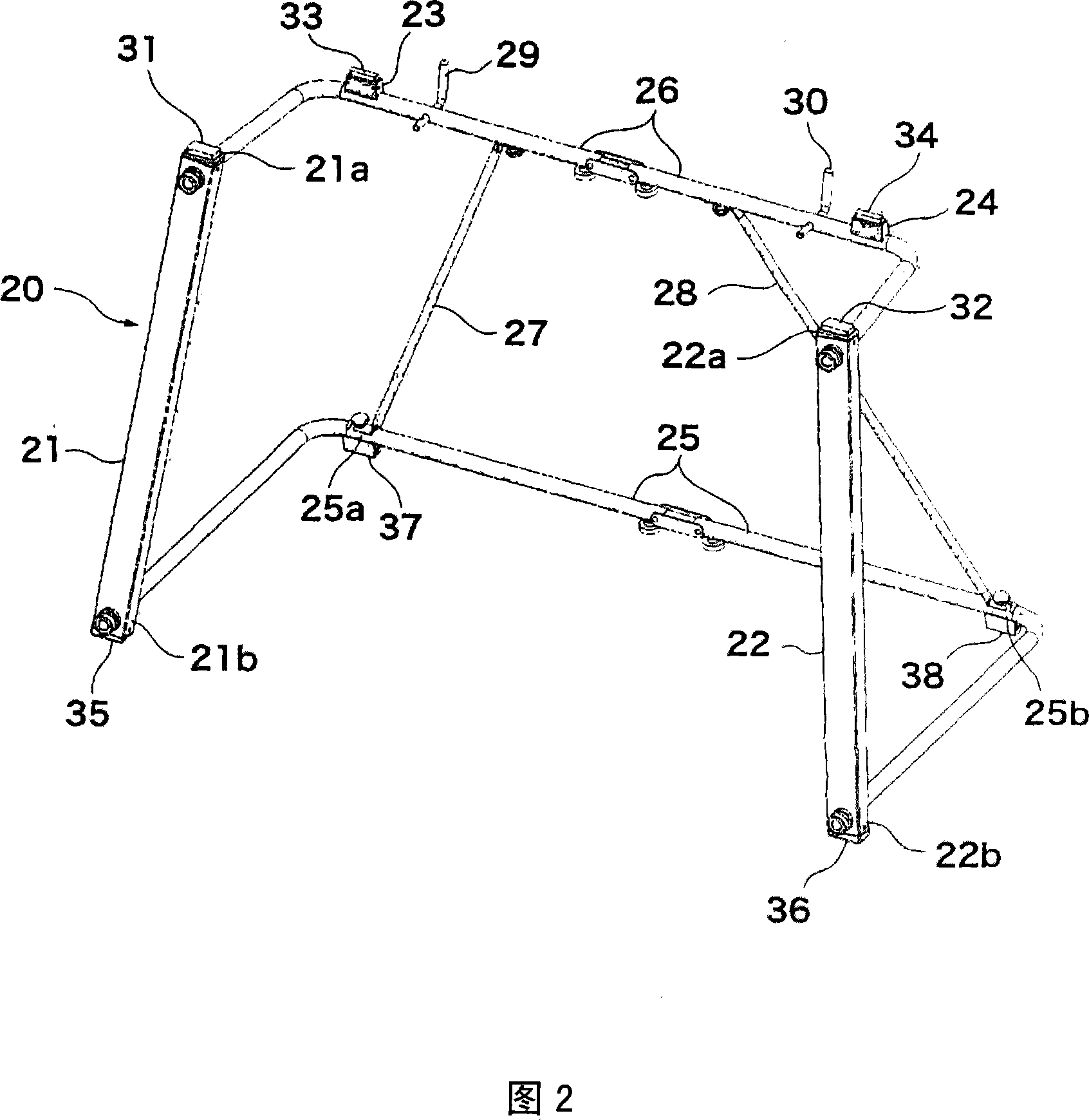
[0032] figure 2 is a perspective view of the bracket 20. The bracket 20 is mainly assembled with a left support 21...
no. 2 Embodiment approach
[0053] Fig. 6(a) is a schematic bottom view of a state in which the musical instrument system according to the second embodiment of the present invention is arranged in a standard position. In the second embodiment, the shapes of the upper ends of the left strut 21 and the right strut 22 are different from those in the first embodiment, and the stoppers 29 and 30 can be omitted. Other configurations are the same as those of the first embodiment.
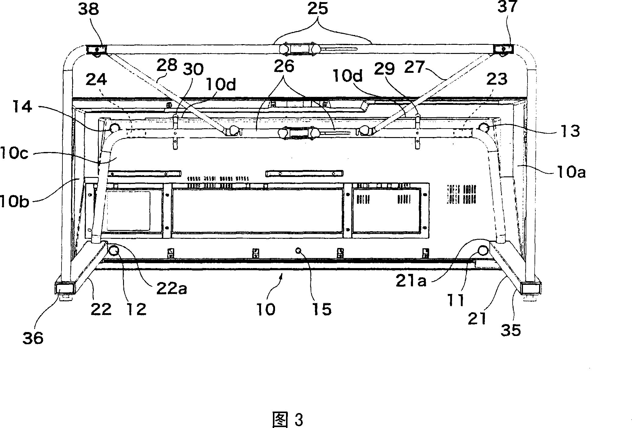
[0054] As shown in FIG. 6( a ), in the second embodiment, the upper end portion 121a of the left pillar 21 and the upper end portion 122a of the right pillar 22 have a <-shape projecting outward in the left-right direction and forward. The shape of the front side support parts 31 and 32 is arbitrary, for example, it is made to be the same as that of 1st Embodiment. The positional relationship between the protrusions 23 and 24 and the left rear leg 13 and the right rear leg 14 is exactly the same as that of the first embodiment.
[...
no. 3 Embodiment approach
[0060] Fig. 6(b) is a schematic bottom view of the musical instrument system according to the third embodiment of the present invention arranged in a standard position. In this third embodiment, the positions of the left rear leg 13 and the right rear leg 14 are different from those of the first embodiment. Other configurations are the same as those of the first embodiment.
[0061] As shown by the solid line in Fig. 6 (b), in this third embodiment, when the instrument body 10 is placed in the standard position, the left rear leg 13 and the right rear leg 14 are arranged to be located at the protruding portion 23, 24 directly behind. When the musical instrument body 10 is moved forward from the standard position, the forward movement is restricted because the left rear leg 13 and the right rear leg 14 abut against the protrusions 23 and 24 . In addition, the backward movement restriction is realized by the stoppers 29 and 30 as in the first embodiment. Therefore, the moveme...
PUM
 Abstract
Description
Claims
Application Information
 - R&D
- Intellectual Property
- Life Sciences
- Materials
- Tech Scout
- Unparalleled Data Quality
- Higher Quality Content
- 60% Fewer Hallucinations
Browse by: Latest US Patents, China's latest patents, Technical Efficacy Thesaurus, Application Domain, Technology Topic, Popular Technical Reports.
© 2025 PatSnap. All rights reserved.Legal|Privacy policy|Modern Slavery Act Transparency Statement|Sitemap|About US| Contact US: help@patsnap.com


