
Process for using oscillatingmagnetic separation barrel mineral concentration

A magnetic separator, swinging technology, applied in magnetic separation, solid separation, chemical instruments and methods, etc., can solve the problems of high magnetic iron content in tailings and low iron selection grade.

Inactive Publication Date: 2007-11-28
衣大明
View PDF0 Cites 2 Cited by
  • Summary
  • Abstract
  • Description
  • Claims
  • Application Information

AI Technical Summary

Problems solved by technology

The existing dry separation process cannot effectively solve the magnetic agglomeration phenomenon in the beneficiation process, resulting in problems such as low iron grade and high magnetic iron content in tailings

Method used


Image

  • Process for using oscillatingmagnetic separation barrel mineral concentration

Examples


Embodiment Construction

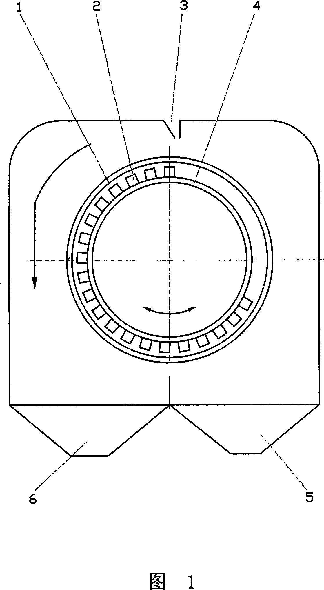
[0007] This process is to continuously add ground magnetic iron ore powder to the magnetic separation cylinder 3, and separate the magnetic minerals and non-magnetic minerals through the rotation of the magnetic separation cylinder outer selection cylinder 1, and then pass through the non-magnetic minerals discharge port 6 Flow out from the discharge port 5 of the magnetic minerals, and when the outer cylinder rotates for 1 revolution, the inner cylinder 4 swings back and forth around its own axis, the swing angle is 30°, and the swing speed is 230 times / min. 2 is the permanent magnet on the inner tube 4 surface.


PUM


Abstract

The present invention relates to magnetic mineral separation, and is especially mineral drilling process with swing type magnetic separating cylinder. The technological process includes adding material to the magnetic separating cylinder, rotating the outer magnetic separating cylinder to separate magnetic mineral from non-magnetic mineral, and swinging the inner cylinder reciprocally in the swinging angel of 25-35 deg and swinging speed of 80-260 times each min. Swinging the inner cylinder can reach the effect similar to that of doubling pole number of the magnetic system so as to avoid magnetic coagulation, raise the grade of separated iron mineral and lower the iron content in the tailing.

Description

technical field [0001] The invention relates to a process for beneficiation of minerals by using a swing-type magnetic separation cylinder, and relates to a process of magnetic mineral beneficiation. Background technique [0002] The current magnetic iron beneficiation process is divided into wet separation and dry separation. Due to the limitation of water resource bottleneck, the existing traditional wet separation equipment and technology are gradually being replaced by dry separation process. The existing dry separation process cannot effectively solve the magnetic agglomeration phenomenon in the beneficiation process, resulting in problems such as low iron grade and high magnetic iron content in tailings. Contents of the invention [0003] The object of the present invention is to solve the phenomenon of magnetic agglomeration and provide a kind of ore dressing process. [0004] The mineral separation process using the swing magnetic separation cylinder is to feed ma...

Claims


Application Information

Patent Timeline
IPC IPC(8): B03C1/12
Inventor 衣大明
Owner 衣大明
Learn More