Wireless kilowatt meter reading-out system
A wireless meter reading and wireless chip technology, applied in signal transmission systems, instruments, etc., can solve the problems of long-distance meter reading that cannot be effectively solved, high manufacturing costs, and high power consumption of power amplifier circuits. Low manufacturing and use costs, long-distance meter reading, and low energy consumption
- Summary
- Abstract
- Description
- Claims
- Application Information
AI Technical Summary
Problems solved by technology
Method used
Image
Examples
Embodiment 1
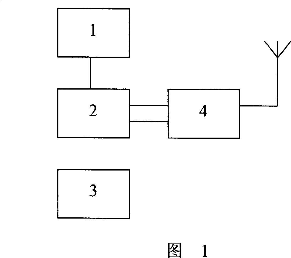
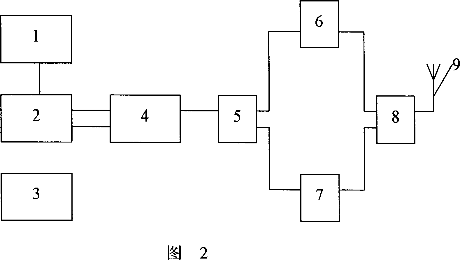
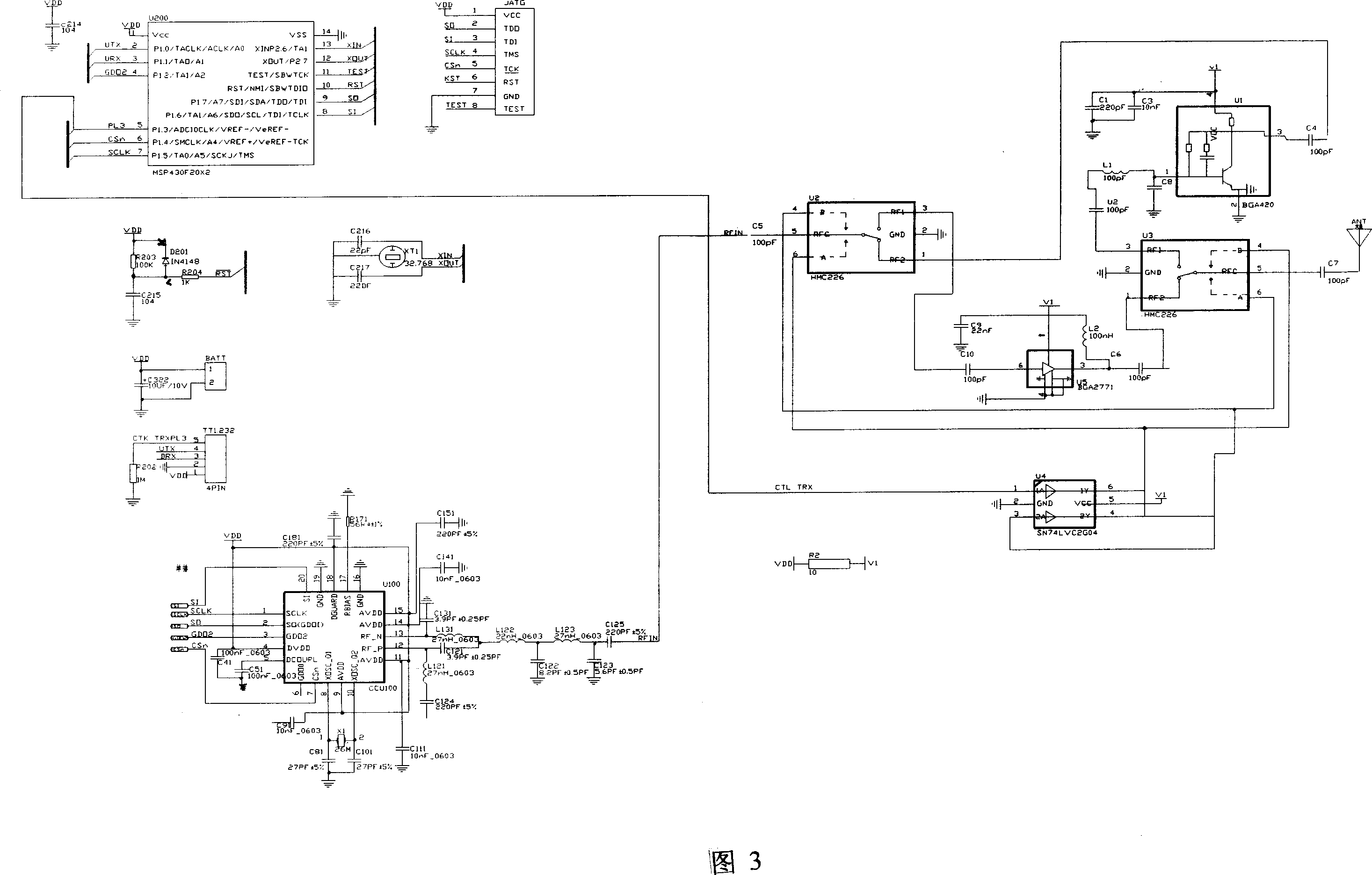
[0009] Embodiment 1: with reference to accompanying drawing 2 and 3. The wireless meter reading system, single-chip microcomputer 2 is the prior art, and will not be described here. The reset terminal of the single-chip microcomputer 2 is connected with the signal terminal of the reset circuit 1, the debugging interface of the single-chip microcomputer 2 is connected with the signal terminal of JTAG3, the data interface of the single-chip microcomputer 2 is connected with the signal terminal of the wireless transceiver circuit 4, and the wireless transceiver circuit 4 is composed of a wireless chip and a matching circuit configuration. The wireless transceiver circuit 4 is produced by Hangzhou Lierda Technology Co., Ltd. The signal end of the wireless transceiver circuit 4 is connected with the signal end of the high frequency switch 5, and the signal input end and the signal output end of the high frequency switch 5 are respectively connected with the signal output end of th...
Embodiment 2
[0010] Embodiment 2: On the basis of Embodiment 1, the signal terminal RFIN of the wireless transceiver circuit 4 is connected to pin 5 of the high-frequency switch 5, and pins 4 and 6 of the high-frequency switch 5 are respectively connected to pins 4 and 6 of the high-frequency switch 8. 4 pins and 6 pins of the pin and the NOT gate circuit, 1 pin of the NOT gate circuit is connected to the signal end of the wireless chip in the wireless transceiver circuit 4, and 3 pins and 6 pins of the NOT gate circuit are connected in parallel. Pin 1 and pin 3 of high frequency switch 5 and high frequency switch 8 are respectively connected to the signal input and output terminals of low noise amplifier circuit and power amplifier circuit, and pin 5 of high frequency switch 8 is connected to antenna 9 through capacitor.
Embodiment 3
[0011] Embodiment 3: On the basis of Embodiment 1 and 2, the power amplifier circuit is composed of capacitor C 9 、C 10 、C 6 , inductance L 2 and U 5 Composition, C 10 One end is connected to pin 3 of high frequency switch 5, C 10 The other end is connected to U 5 The 6-pin, U 5 3 pins connected to L 2 one end and C 6 end of the L 2 The other end of the C 9 one end and U 5 ground terminal, C 9 The other end of the ground, C 6 The other end of the high-frequency switch is connected to pin 81; the low-noise amplifier circuit consists of a capacitor C 1 ~C 4 、C 8 and U 1 Composition, C 4 One end of the high-frequency switch 5 pin 1, C 4 The other end of the U 1 The 3 pins, U 1 4 pins connected to C 1 、C 3 end of the C 1 、C 3 The other end is connected to ground, U 1 Pin 1 connects to C 8 , L 1 end of the C 8 the other end and the U 1 2 pins are grounded, L 1 The other end is connected to C 2 end of the C 2 The other end is connected to pin 3 of the...
PUM
 Abstract
Description
Claims
Application Information
 - R&D
- Intellectual Property
- Life Sciences
- Materials
- Tech Scout
- Unparalleled Data Quality
- Higher Quality Content
- 60% Fewer Hallucinations
Browse by: Latest US Patents, China's latest patents, Technical Efficacy Thesaurus, Application Domain, Technology Topic, Popular Technical Reports.
© 2025 PatSnap. All rights reserved.Legal|Privacy policy|Modern Slavery Act Transparency Statement|Sitemap|About US| Contact US: help@patsnap.com


