Emergency braking device for elevator and elevator

An emergency braking and elevator technology, which is applied in the field of elevators, can solve the problems of incompatibility of friction parts, inability to ensure friction, and poor pressing force, etc., and achieve high reliability

Active Publication Date: 2010-07-21
HITACHI LTD
View PDF9 Cites 0 Cited by
  • Summary
  • Abstract
  • Description
  • Claims
  • Application Information

AI Technical Summary

Problems solved by technology

[0009] In the above-mentioned conventional technology, when the emergency brake is operated, uneven pressing force is generated in the sliding surface of the friction member, and there is a possibility that the rotation of the friction member cannot be suppressed due to the rotational force acting on the friction member.
That is to say, when the rotational force caused by friction exceeds the holding force of the friction member fixed by riveting, it will cause the friction member to rotate, and the friction force acting between the friction member and the guide rail cannot be ensured, so that it cannot be obtained. appropriate deceleration
In particular, when the load is further increased with the increase of the falling mass, it is necessary to increase the braking force accordingly. In this way, the pressure difference in the sliding surface of the friction member is further increased, making it more difficult to suppress the friction of the friction member. to rotate
[0010] In addition, rail cutting powder generated during braking may affect the frictional force depending on how the friction parts are installed.
Specifically, when cutting powder stays in the brake part, the sliding heat will be transferred to the support part of the brake part through the cutting powder, causing thermal deformation of the support part, resulting in the failure of the friction part to contact the guide rail uniformly, This results in a decrease in friction

Method used


Image

  • Emergency braking device for elevator and elevator
  • Emergency braking device for elevator and elevator
  • Emergency braking device for elevator and elevator

Examples


Embodiment Construction

[0038] Hereinafter, the emergency braking device for an elevator according to the present invention will be described with reference to the drawings.

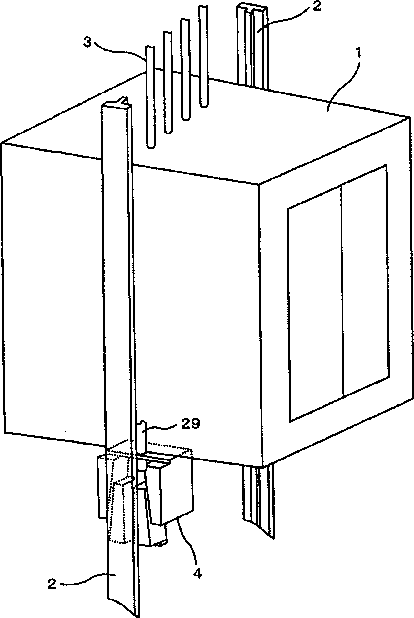
[0039] figure 1 It is a perspective view of the elevator car 1 of the elevator and the emergency braking device installed at the lower part of the elevator car 1. The elevator car 1 used to carry passengers is connected to the uppermost floor of the building (not shown) through the sling 3 drive system connection. In this figure, for ease of understanding, the detailed illustration of the elevator door opening and closing equipment and the outer frame is omitted.

[0040] On both sides of the hoistway, a pair of guide rails 2 are provided to guide the elevator car 1 when going up and down. A pair of emergency stoppers 4 are provided at the lower part of the elevator car 1, and the pair of emergency stoppers clamp the T-shaped longitudinal rails of the respective guide rails 2 formed in a T-shaped cross-sectional shape. The p...


PUM


Abstract

Providing a emergency braking device for elevator and elevator, a frictional part is fixed in a braking piece firmly to improve the reliability of stopping elevator car when emergency braking. In the mentioned emergency braking device, the braking piece (5) compresses the guide rail (2) to generate braking force when occurring emergency so as to stop the elevator car (1). The mentioned device includes frictional part (12) which has the shape to resects part of cylinder to form planar excision surface (15a); braking piece (5) , which clips the guide rail (2) through keeping the support part (5a) of the frictional part (5); elastomer (6) , which compresses the braking piece (5) on the guide rail (2). The frictional part (12) sets that its cylindrical end face is compressed on the guide rail(2), and the excision surface (15a) is parallel to the lifting direction of the elevator car (1).

Description

technical field [0001] The present invention relates to an emergency braking device for an elevator and an elevator, in particular to an elevator suitable for actuating the emergency braking device for an elevator when the speed of the elevator exceeds a predetermined speed. Background technique [0002] On the elevator, it is obligatory to install a safety device that stops the elevator car at an appropriate deceleration when the descending speed of the elevator car exceeds a certain speed, that is, an emergency braking device. [0003] The emergency braking device is a brake that uses two trapezoidal friction parts on the inner side surrounded by elastic body. When the speed of the elevator car exceeds a certain speed, the two brake parts are pressed and installed on the wall of the elevator passage The guide rails for elevators on the road are brake devices that use force generated by elastic deformation to generate braking force. Conventionally, brake parts have been mad...

Claims


Application Information

Patent Timeline
Patent Type & Authority Patents(China)
IPC IPC(8): B66B5/22
Inventor 佐藤五郎岩佐正明宫田弘市大森贡座间秀隆
Owner HITACHI LTD
Why Eureka
Try Eureka