Eureka AIR delivers breakthrough ideas for toughest innovation challenges, trusted by R&D personnel around the world.

Coagulation-separation apparatus

A separation device and separation box technology, applied in the directions of sedimentation separation, separation method, and sediment separation by centrifugal force, can solve the problem of low processing efficiency and achieve the effect of reducing manufacturing cost

Inactive Publication Date: 2007-11-14
NISHIHARA ENVIRONMENT TECH
View PDF1 Cites 2 Cited by
  • Summary
  • Abstract
  • Description
  • Claims
  • Application Information

AI Technical Summary

Problems solved by technology

Therefore, there is a problem that the entire equipment site must be large because the solid-liquid separation tank is an additional necessary equipment, and because the size of the solid-liquid separation tank is at least the same as that of the coagulation reaction tank
Furthermore, because the flocs are separated from the water to be treated by using gravity, the treatment cannot proceed at a rate beyond the settling of the flocs
Therefore, the processing efficiency is not high

Method used


Image

  • Coagulation-separation apparatus
  • Coagulation-separation apparatus
  • Coagulation-separation apparatus

Examples


example

[0094] first instance

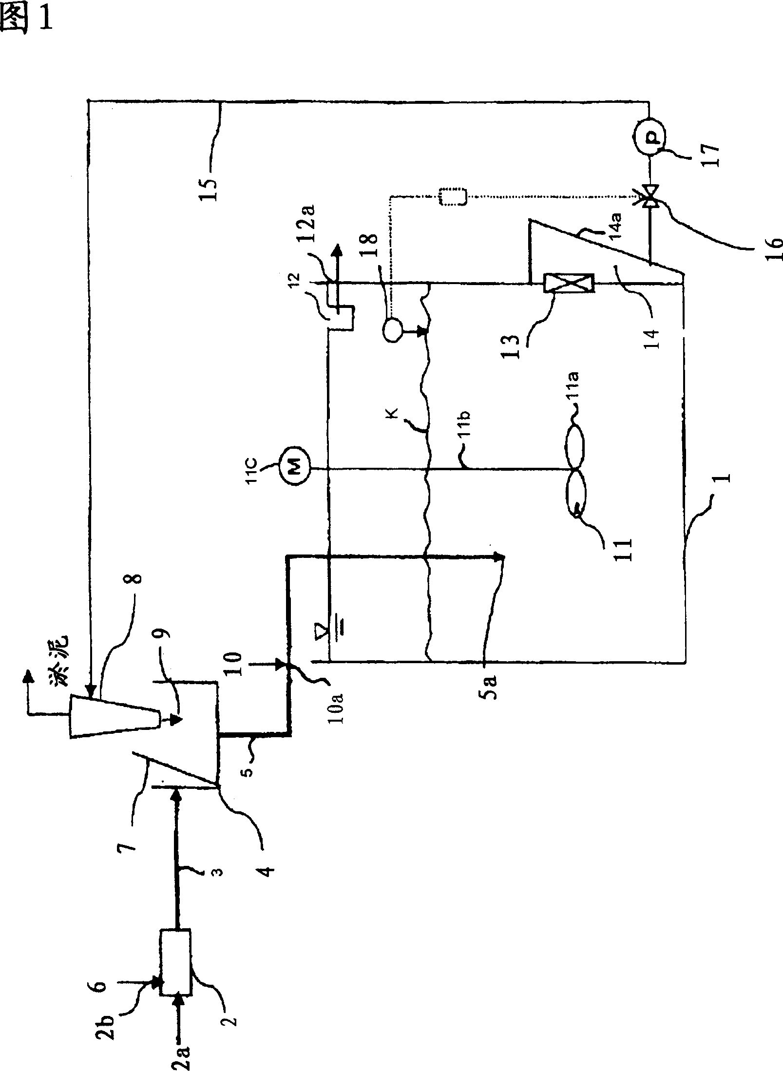
[0095] A first embodiment of the coagulation and separation device shown in FIG. 1 was implemented. As a condition of implementation, the inflow water of the first sedimentation tank in the sewage treatment plant is used as raw water. Add PAC to the raw water at an addition rate of 10mg / L (by Al 2 o 3 l conversion) to form a coagulant (inorganic coagulant) 6. Sand was added to the raw water at a concentration of 3000mg / L to form a high specific gravity material9. The polymer coagulant was added to the raw water at a concentration of 1 mg / L to form coagulant aid 10. Under this condition, the results regarding the relationship among influent water volume, residence time in the device, raw water SS, treated water SS, SS removal rate, sludge concentration, and discharged sludge volume were obtained, as shown in Table 1 . As seen from Table 1, the SS removal rate became 80% or higher within 10 minutes of residence time in the apparatus. Therefore, hig...


PUM


Abstract

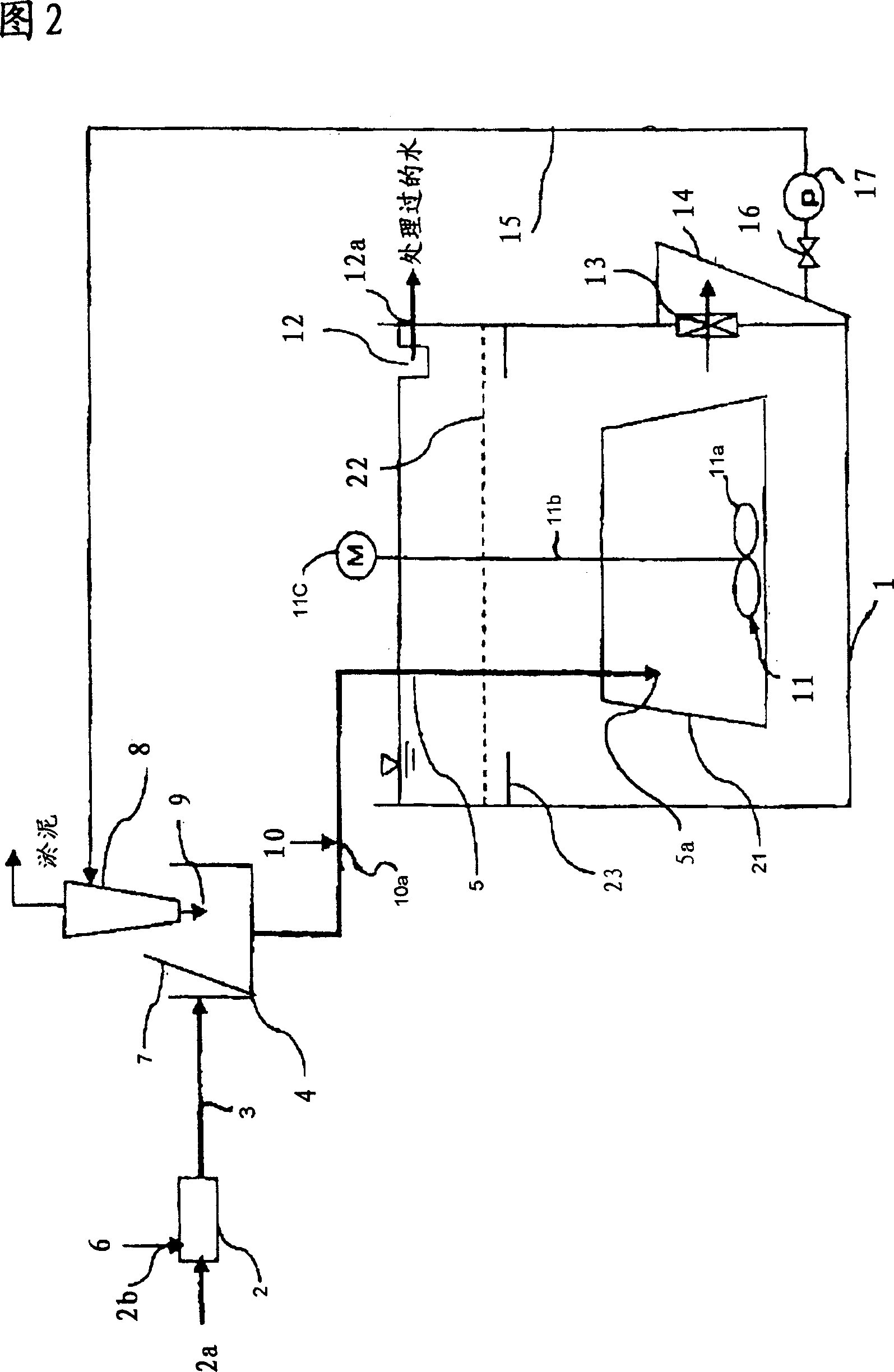
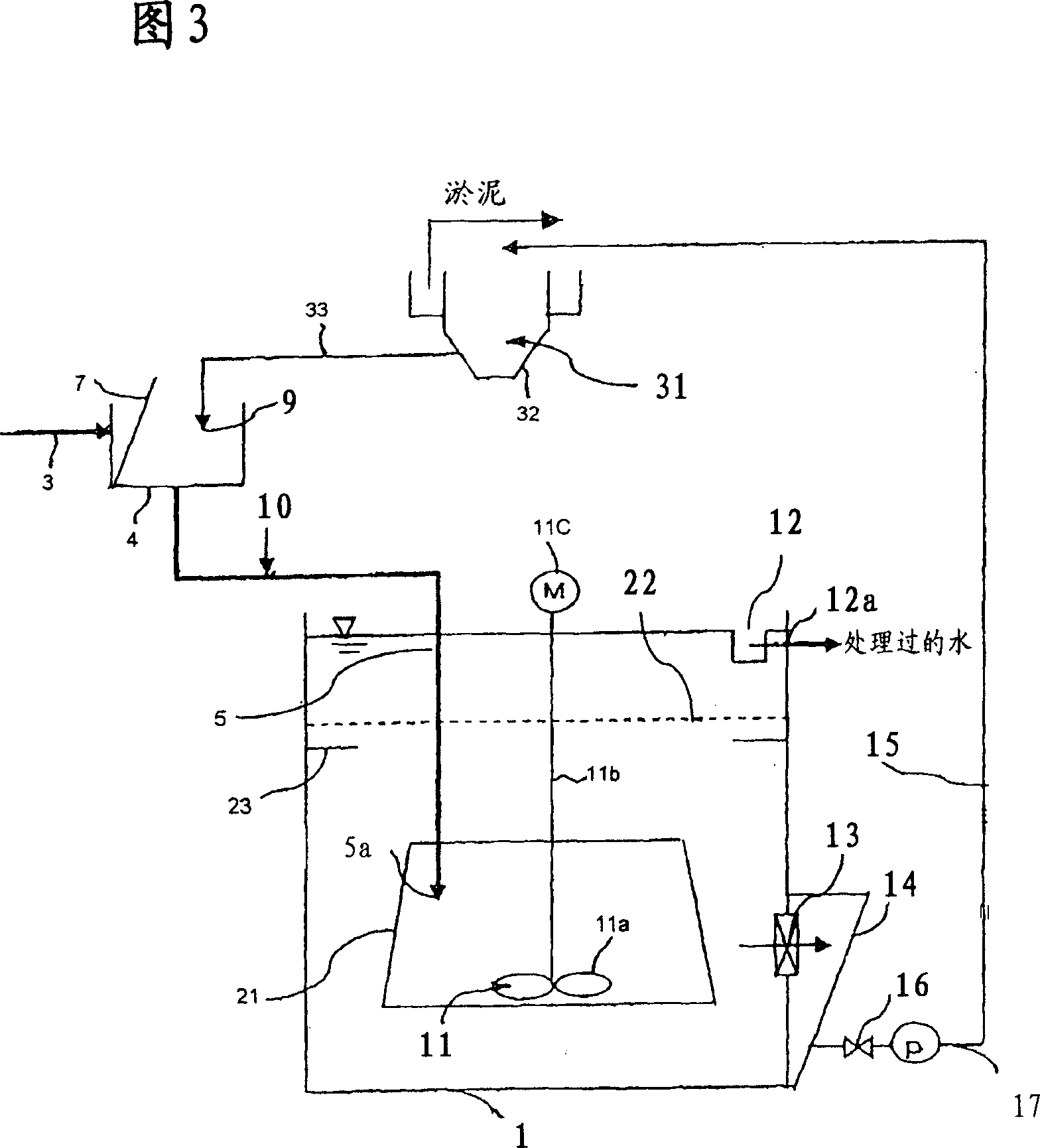
A coagulation-separation apparatus has a coagulation-separation tank (1). Raw water flows from a mixing tank (2) to a coagulation-separation tank (1) through a raw water introduction pipe (3), a facility (4) for adding a high specific gravity material and a raw water introduction pipe (5). The coagulation-separation tank (1) is provided with a water-flow generator which agitates water to be treated to generate a water flow. The coagulation-separation tank (1) has a discharge port (13) for a sludge and a box (14) for collecting sludge in the lower portion thereof, wherein a sludge inside the box (14) for collecting sludge is transferred to a separator (8) through a sludge transfer pipe (15). The separator (8) is used for separating a high specific gravity material (9) from the sludge and supplying it to the facility (4) for adding a high specific gravity material.

Description

technical field [0001] The invention relates to a coagulation and separation device. In this coagulation and separation device, the starting water (such as raw water, influent water) containing suspended matter such as colloids or particles to be treated is mixed with a coagulant, and the suspended matter is coagulated to form floc (coagulated sludge), and then The flocs are separated from the starting water by solid-liquid separation. In this way, clean water can be continuously obtained. Background technique [0002] A common coagulation and separation device of this type is equipped with a coagulation reaction tank. The initial water containing suspended solids to be treated flows into the coagulation reaction tank through the raw water inlet pipe. A coagulant is added from a coagulant supply device to the water to be treated flowing into the coagulation reaction tank. An insoluble additive such as sand is supplied from the additive supply device to the water to be tr...

Claims


Application Information

Patent Timeline
Patent Type & Authority Applications(China)
IPC IPC(8): B01D21/26B01D21/28B01D21/01
CPCB01D21/245C02F2305/12B01D21/286B01D21/2488B01D21/2444C02F2303/24B01D21/2427C02F1/5281C02F1/5245B01D21/26B01D21/0012B01D21/0042B01D21/32C02F2301/046B01D21/01B01D21/28C02F1/52
Inventor 山田康夫京才俊则森川则三佐藤稔西原幸志永松真一大浦正美樱井立真间濑博子
Owner NISHIHARA ENVIRONMENT TECH
Why Eureka
Eureka Blog
Learn More