
Optical interference measuring device and its method

A technology of optical interference and measuring devices, applied in the field of precision measurement, to achieve the effect of improving phase sensitivity

Inactive Publication Date: 2007-11-14
ZHEJIANG UNIV
View PDF0 Cites 7 Cited by
  • Summary
  • Abstract
  • Description
  • Claims
  • Application Information

AI Technical Summary

Problems solved by technology

Due to the limitation of measurement accuracy, the only way to improve the sensitivity of phase measurement is to increase the measured optical power

Method used


Image

  • Optical interference measuring device and its method
  • Optical interference measuring device and its method
  • Optical interference measuring device and its method

Examples


Embodiment Construction

[0019] Specific embodiments of the present invention will be described in detail below in conjunction with the accompanying drawings.

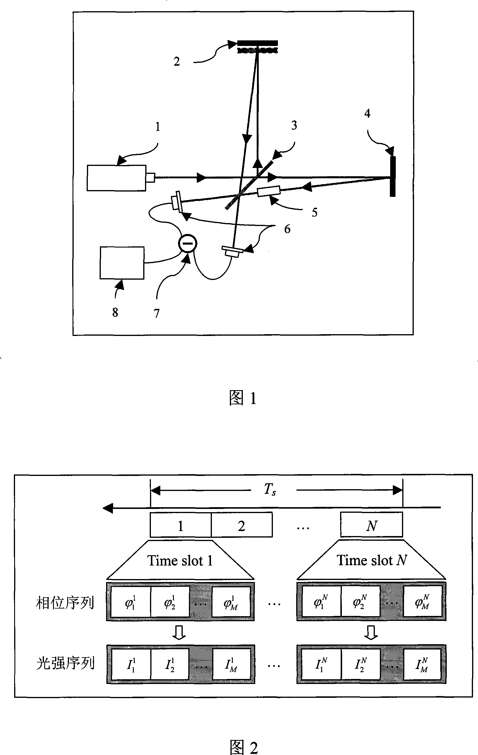
[0020] The working principle of a general Michelson interferometer is as follows: the coherent light source generated by the laser 1 passes through a beam splitter to form two interference arms, and a phase sensing unit is installed on one of the arms, and the phase sensing unit can be a moving mirror 2, or It can be achieved by other methods. and the other as a reference arm. When the coherent light of the two arms interferes again, the phase difference of the two arms will lead to a change in the output light intensity. The light intensity measured by the detector 6 is finally used to obtain the phase change by using the relationship between the light intensity and the phase.

[0021] As shown in Figure 1, the optical interferometry device includes a laser 1, a first reflector 2, a first half-reflective beam splitter 3, a second reflector 4...


PUM


Abstract

The present invention discloses an optical interference measuring device and the method. The coherent light beam produced by the laser is separated into two coherent light beams by the first transflective beam splitter, wherein a coherent light beam generates a phase change by the moving of the first reflecting mirror, the other coherent light beam enters into the phase modulation component through the reflecting mirror, then the transflective beam splitter passed by the two coherent light beam outputs two interference light beams, the two interference light beam changes to electrical signal by the detection of the detector, the electrical signal realizes the measuring of the phase change by the first difference equipment and relevant instruments. The invention realizes the elevation of the phase sensitivity of the interference measuring using the special-designed pseudorandom phase sequence. It only requires an ordinary coherent light source and the linear optical element, and it has important application foreground in the fields of gravitational wave detection, micro-nanometer displacement measurement, optical fiber gyroscope and optical fiber sonar detection.

Description

technical field [0001] The invention relates to the field of precision measurement realized by the principle of optical interference, in particular to an optical interference measurement device and a method thereof. Background technique [0002] Precision measurement is a technology of great significance in scientific research and industrial production, among which precision measurement based on the principle of optical interference is especially widely used. The basic principle of this interferometry is very simple. A beam splitter is used to divide a beam of coherent light into two beams, one of which is used as a reference beam, and the other beam passes through a phase modulator to generate a phase difference. The two beams of light are related to the physical quantity, and then the two beams of light converge again. Due to the generation of phase difference, the two beams of light gathered together interfere, and the output light intensity changes with the transformatio...

Claims


Application Information

Patent Timeline
Patent Type & Authority Applications(China)
IPC IPC(8): G01B9/02
Inventor 符建
Owner ZHEJIANG UNIV
Learn More