Vector correcting method for non-gyro accelerometer array mounting error
A technology for accelerometer and installation error, which is applied in the direction of speed/acceleration/shock measurement, measurement of acceleration, testing/calibration of speed/acceleration/shock measurement equipment, etc. No problems such as installation error of gyro accelerometer array
- Summary
- Abstract
- Description
- Claims
- Application Information
AI Technical Summary
Problems solved by technology
Method used
Image
Examples
Embodiment Construction
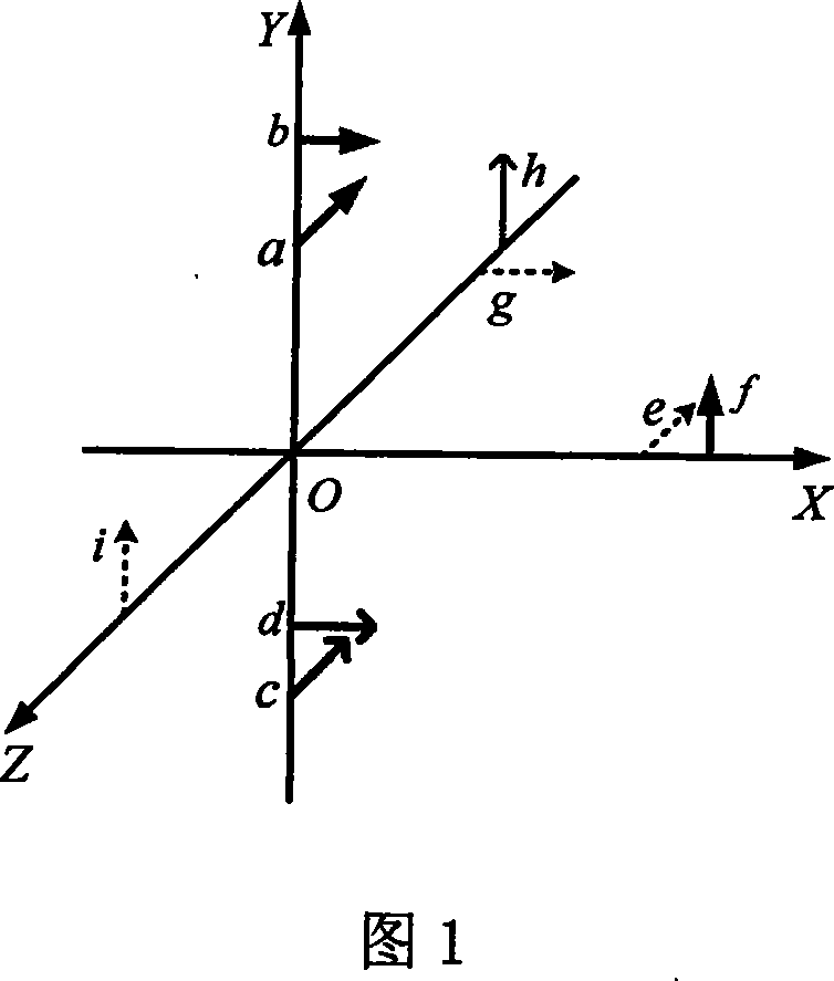
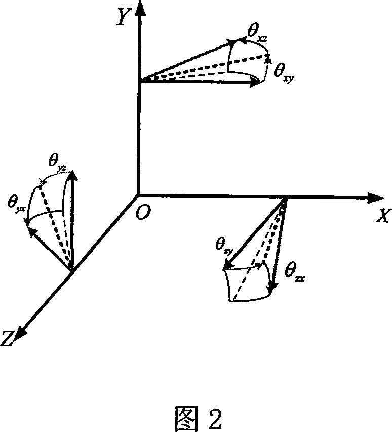
[0059] Taking the 9 accelerometer array as an example, the 9 accelerometers are divided into 3 groups, the accelerometers a, b, f are a group, the accelerometers c, d, h are a group, and the accelerometers e, g, i are a group ,As shown in Figure 1. In the accelerometer cube array, ideally the sensitive directions of the accelerometer groups a, b, f, c, d, h, e, g, i are orthogonal, but it cannot be realized in the actual installation, so the accelerometer groups a, b , the actual sensitive direction of f, c, d, h, e, g, i is non-orthogonal, which is the non-orthogonal coordinate system a.
[0060] There is no vector correction method for the installation error of the gyro accelerometer array, design any group in the accelerometer array—accelerometer group j, when the installation orientation error and installation position error are not compensated, the output specific force of the accelerometer group j is A j ** , when the installation orientation error is not compensated, ...
PUM
 Abstract
Description
Claims
Application Information
 - R&D
- Intellectual Property
- Life Sciences
- Materials
- Tech Scout
- Unparalleled Data Quality
- Higher Quality Content
- 60% Fewer Hallucinations
Browse by: Latest US Patents, China's latest patents, Technical Efficacy Thesaurus, Application Domain, Technology Topic, Popular Technical Reports.
© 2025 PatSnap. All rights reserved.Legal|Privacy policy|Modern Slavery Act Transparency Statement|Sitemap|About US| Contact US: help@patsnap.com


