
Pressure control valve

A pressure control and valve technology, applied in the direction of fluid pressure control, non-electric variable control, control/regulation system, etc., can solve the problems of large operating torque, slow opening and closing speed, short service life, etc., and achieve simple and reasonable structure, opening and closing The effect of fast closing speed and long service life

Inactive Publication Date: 2007-11-07
池严围
View PDF0 Cites 8 Cited by
  • Summary
  • Abstract
  • Description
  • Claims
  • Application Information

AI Technical Summary

Problems solved by technology

[0002] In the existing technology, the general valve structure includes valve body, valve seat, valve cover, valve stem, flange, valve core, etc., with complex structure, relatively large size, large operating torque, easy leakage, and slow opening and closing speed. Fragile parts lead to short service life

Method used


Image

  • Pressure control valve
  • Pressure control valve
  • Pressure control valve

Examples


Embodiment 1

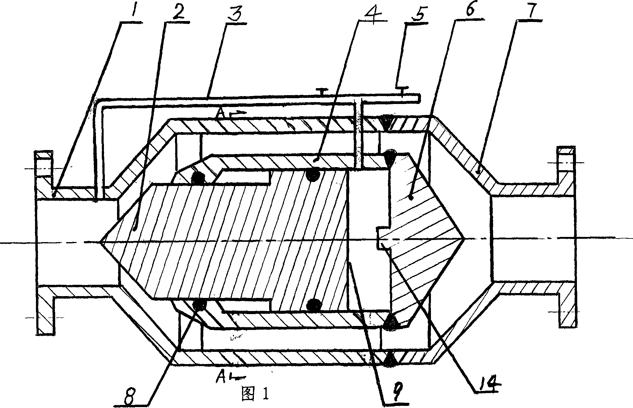
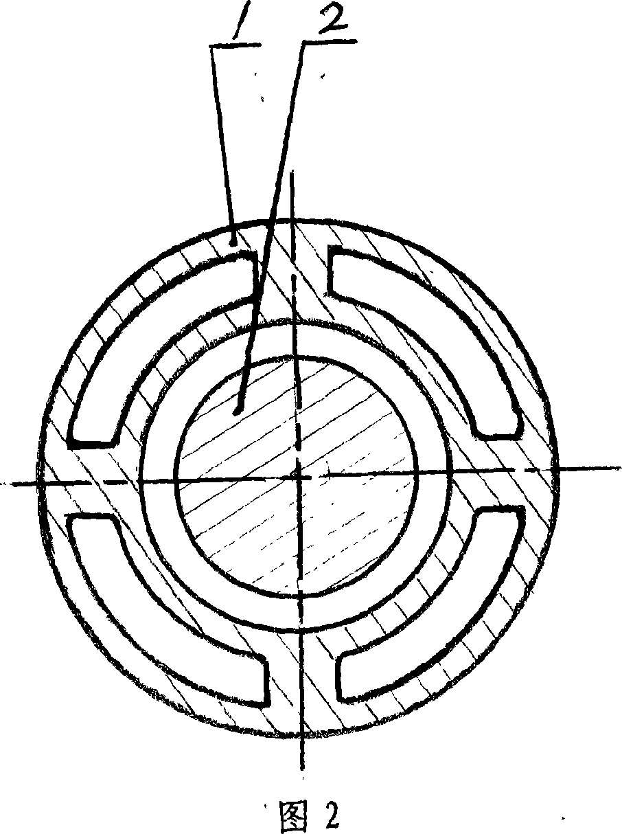
[0018] Referring to the accompanying drawings 1 and 2, it is an external diversion passage type pressure control valve. The two ends of the pressure control valve have inlets or outlets respectively. The front valve body 1 is welded to the rear valve body 7 to form the valve body. The front valve body 1 The valve chamber is connected to the valve cylinder 4 through four connecting beams, and the valve cylinder 4 is welded to the valve cylinder cover 6 to form a valve cylinder. The valve cylinder 4 is slidingly connected to the valve core 2, and its valve core is "T" shape. The structure of the junction between the slider, the spool and the front valve body 1 is a cone spool, and the spool and the matching surface of the front valve body are combined to control the opening and closing and the fluid flow rate, and the matching surface adopts a face seal. A sealing body 8 is inlaid on the connection surface between the valve core 2 and the valve cylinder 4 , and the inner surface ...

Embodiment 2

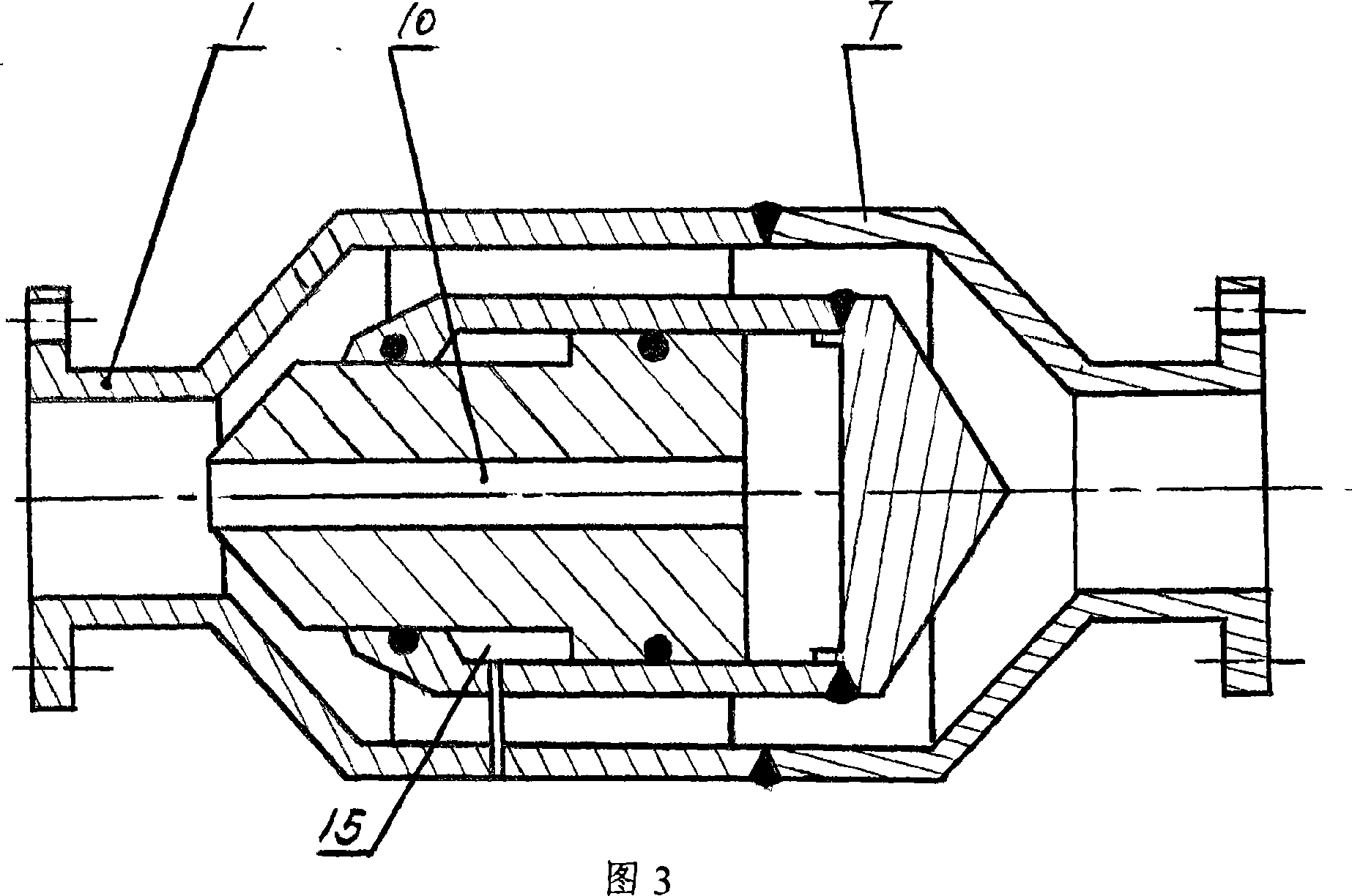
[0020] Referring to accompanying drawing 3, it is an internal diversion passage type pressure control valve, the difference from Embodiment 1 is that the valve cylinder cavity formed between the valve cylinder cover 6 and the pressure bearing surface of the valve core 2 is guided by the internal guide of the valve core 2. The flow passage 10 communicates with the flow cavity at one end of the valve body, and there is a flow pressure control ring cavity 15 between the valve core 2 and the inner wall of the valve cylinder 4, and the cavity is connected with a fluid pressure source through the flow guide path to realize the control valve opening and closing and balance.

Embodiment 3

[0022] Referring to accompanying drawing 4, it is a pressure control valve with a straight cylindrical slider type spool, and the difference from Embodiment 1 is that the spool is a straight cylindrical slider type spool 11 .


PUM


Abstract

The invention provides a pressure controlling valve which the two ends have the inlet or outlet of the fluid. The front valve is connected to the back valve to form the valve. The front valve is connected with the valve barrel canister which is connected with the cover to form the valve barrel. The valve barrel canister is connected with the valve core which is combined with the interface of the front valve. The valve barrel hollow formed by the valve barrel cover and the valve core bearing surface is connected with the inner hollow of the valve by the leading channel. The valve has the simple structure and is not easy to leak, has long using life.

Description

technical field [0001] The invention relates to a valve, in particular to a valve which uses its own fluid pressure to control opening and closing and flow limiting. Background technique [0002] In the existing technology, the general valve structure includes valve body, valve seat, valve cover, valve stem, flange, valve core, etc., with complex structure, relatively large size, large operating torque, easy leakage, and slow opening and closing speed. Fragile parts lead to short service life. Contents of the invention [0003] The purpose of the present invention is to overcome the above disadvantages and provide a pressure control valve with simple and reasonable structure, convenient operation, fast opening and closing speed and long service life. [0004] The purpose of the present invention is achieved by the following measures: the two ends of the pressure control valve have fluid inlets or outlets respectively, the front valve body is connected to the rear valve bo...

Claims


Application Information

Patent Timeline
Patent Type & Authority Applications(China)
IPC IPC(8): F16K1/00F16K31/122
CPCF16K31/124G05D16/106F16K31/1226F16K31/1223F16K1/126
Inventor 池严围
Owner 池严围
Learn More