Anti-disengaging device for air valve controlling rod

A control rod and valve technology, applied in the direction of valve operation/release device, valve device, valve details, etc., can solve the problems of disengagement, car stop, damage to the engine, etc., and achieve the effect of uniform valve lift and prolonging service life

Inactive Publication Date: 2007-11-07
SCHAEFFLER KG +1
View PDF1 Cites 2 Cited by
  • Summary
  • Abstract
  • Description
  • Claims
  • Application Information

AI Technical Summary

Problems solved by technology

Loss of contact could cause the valve control lever to disengage from the valve, with the result that the cylinder involved would be rendered inoperable leading to a stalled car and possible damage to the engine

Method used


Image

  • Anti-disengaging device for air valve controlling rod
  • Anti-disengaging device for air valve controlling rod
  • Anti-disengaging device for air valve controlling rod

Examples


Embodiment Construction

[0076]The figures shown in the drawings are schematic and not to scale. In the following description of FIGS. 1 to 3 , the same or corresponding parts use the same reference numerals.

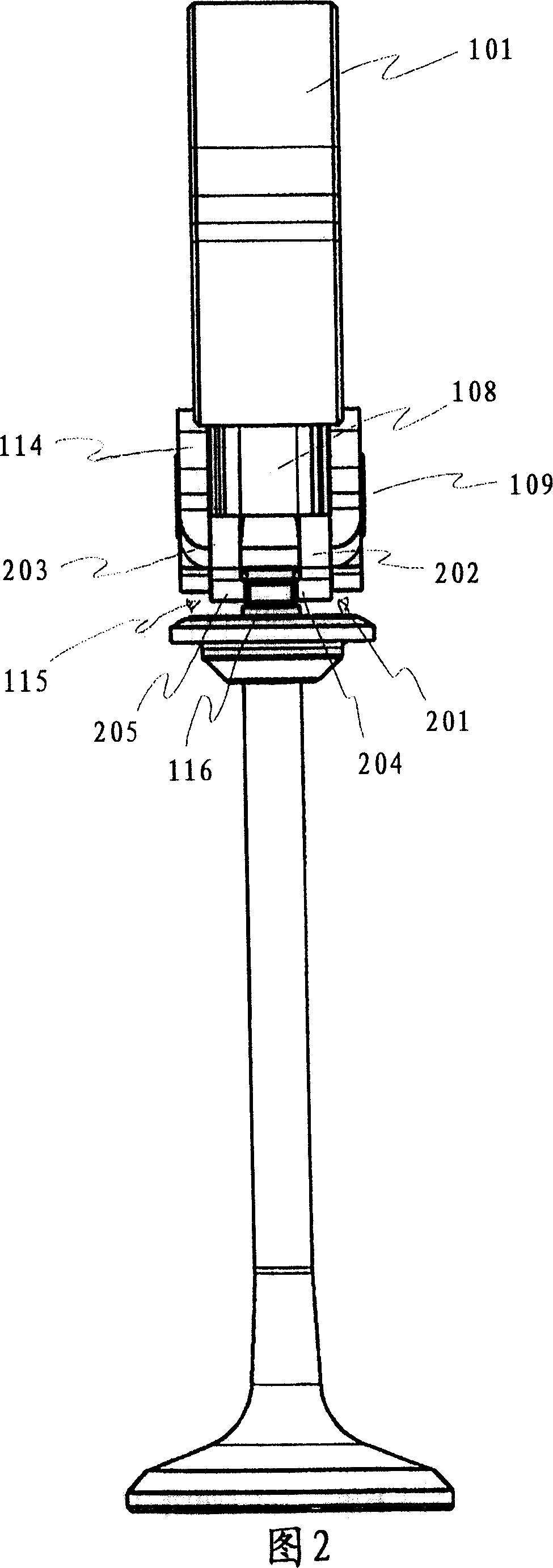
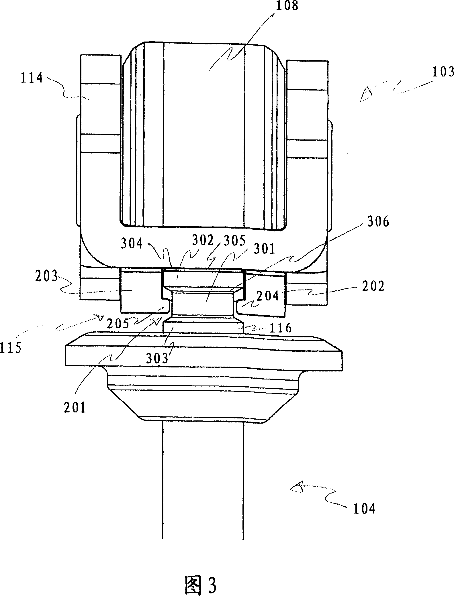
[0077] FIG. 1 shows a side view of a valve train arrangement according to an exemplary embodiment of the invention. This valve train arrangement 100 has some parts including a cam 101 , a support 102 , a valve control lever 103 and a valve 104 . The cam 101 has an essentially circular shape with a projection in a subregion 105 . The contour in this portion of the protrusion 105 is at a greater distance from the cam axis of rotation 106 than the contour in the substantially circular region of the cam 101 is.

[0078] The cam with the axis of rotation 106 is fastened to a housing not shown in FIG. 1 . The circumference of the cam 107 rolls on a roller 108 or a roller 108 of the valve control lever 103 during rotation about the axis of rotation 106 . The roller 108 is mounted rotatably about a...


PUM


Abstract

The invention relates to a air drain control lever for operating air drain, wherein the air drain control lever has a base body and a joint element which is set on an end region of the base body and is designed to keep the distance between the base body and the air drain below a maximum value able to be preset as the base body moving.

Description

technical field [0001] The present invention relates to a valve control rod, a valve, a valve train arrangement and a method for preventing disengagement of the valve control rod from the valve. Background technique [0002] Valve trains are used in internal combustion engines to control gas exchange. The valve train includes the intake and exhaust valves, the valve springs that close the intake and exhaust valves, the cam drive mechanism, and the transmission mechanism. Valve control devices of various designs are known. There is, for example, a pushrod control in which the force is transmitted from the cam to the individual valves via the pushrod. [0003] There are also drawbar or rocker controls, in which the cam force is transmitted via a lever that pivots between the valve and the cam, usually mounted on the cylinder head. [0004] Rocker arm controls are also known in which the transmission, the rocker arm, pivots about a rocker arm axis arranged between the camsha...

Claims


Application Information

Patent Timeline
Patent Type & Authority Applications(China)
IPC IPC(8): F01L1/18
CPCF01L1/053F01L1/185F16K31/52408F01L2001/187F01L1/2405
Inventor S·莫克R·特基格雷贝尔K·阿克斯特黑尔姆K-D·富克斯
Owner SCHAEFFLER KG
Why Eureka
Try Eureka