
Floor lock latch

A technology of floor locks and boards, which is applied to floors, buildings, building structures, etc. It can solve the problems that the tenons cannot be deformed, gaps appear on the surface, and the floor locks are easy to loosen, and the effect is obvious and the surface is smooth.

Inactive Publication Date: 2007-11-07
朱赛瑜
View PDF1 Cites 14 Cited by
  • Summary
  • Abstract
  • Description
  • Claims
  • Application Information

AI Technical Summary

Problems solved by technology

[0003] However, when the existing floor lock is used on an uneven ground, whether it is horizontal or angle clamping or up and down vertical clamping, because the tenon cannot be deformed, the surface will be flanged due to extrusion, or there will be gaps on the surface , affect the appearance and life of the floor
At the same time, the surface of the floor on the uneven ground will vibrate when it is subjected to external force. Since the tenon cannot be deformed accordingly, the floor lock is easy to loosen during the vibration.

Method used


Image

  • Floor lock latch
  • Floor lock latch
  • Floor lock latch

Examples


Embodiment Construction

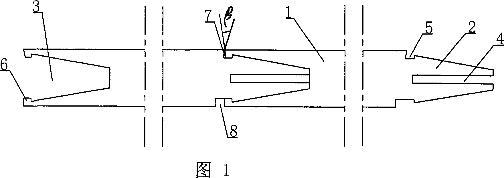
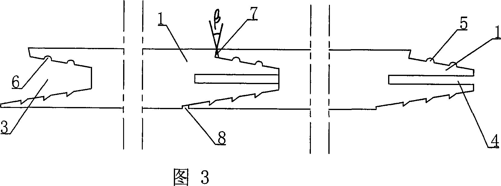
[0025] Embodiments 1 to 6 are cases where the tenon 2 and the slot 3 of the floor lock are arranged horizontally relative to the plane of the board body 1 .

[0026] As shown in Figure 1 is the first embodiment of the floor lock of the present invention, it is provided with a tenon 2 on one side of the plate body 1, the cross section of the tenon 2 is a conical protrusion, and on the other side corresponding to this side A card slot 3 matching the tenon 2 is provided, and the head of the tenon 2 is provided with a groove 4 that allows elastic deformation of the tenon when it is squeezed by the card slot 3, and locking protrusions are provided on the upper and lower tenon surfaces of the tenon 2 Protrusion or indentation 5, and corresponding indentation or protrusion 6 matching the locking protrusion or indentation 5 of the tenon 2 is set in the head end of the slot 3. In this embodiment, the locking protrusion or indentation 5 is A groove with a square cross-section is symmetr...


PUM


Abstract

The present invention relates to connection of boards, and is especially one kind of floor board connecting structure. The floor board connecting structure includes a tenon with slot for the tenon to produce elastic deformation on one side of the board, a mortise on the opposite side for matching with the tenon in one other board, and one locking mechanism in the joint between the tenon and the mortise. The floor board connecting structure can combine floor boards closely and smoothly.

Description

Technical field [0001] The invention relates to a connection structure between boards, in particular to a floor lock. Background technique [0002] The existing floor that is internally fixed by means of the mortise horizontally snapped into the card slot is difficult to install when assembled to the edge, and even if the installation is barely completed, it is difficult to take it out for maintenance in the future. Patent 03259766.5 discloses a chain lock floor, which provides a solution. The upper part of the floor body extends laterally to form a downwardly protruding tenon and an adjacent groove. In the direction of the other side parallel to it, The upwardly protruding tenon and the adjacent groove are formed by the lateral extension of the lower part of the floor board. The tenon and the groove on one side cooperate with the groove and the tenon on the other side of the adjacent floor respectively to form a chain structure. [0003] However, when the existing floor lo...

Claims


Application Information

Patent Timeline
Patent Type & Authority Applications(China)
IPC IPC(8): E04F15/02
Inventor 朱赛瑜
Owner 朱赛瑜
Learn More