


Quick Research
Generate reliable direction feasibility study reports for your R&D in just a few steps.

Technical Q&A
Discover and master advanced knowledge NOW. Basics, ideas, possibilities, all at once.

Find Solutions
As an expert in R&D theories, this can generate solutions to your technical problems instantly.

Evaluate Feasibility
Analyze your overall solution with one click, know your potential R&D risks in advance.

Monitor Landscape
Get weekly tech updates, stay abreast of the latest tech innovations and key insights.
Systems for managing electrical power
A technology of electrical coupling and direct current, applied in control systems, electrical components, motor control, etc., can solve problems such as transformer phase shift
- Summary
- Abstract
- Description
- Claims
- Application Information
AI Technical Summary
Problems solved by technology
Method used
Image

Examples
Embodiment Construction
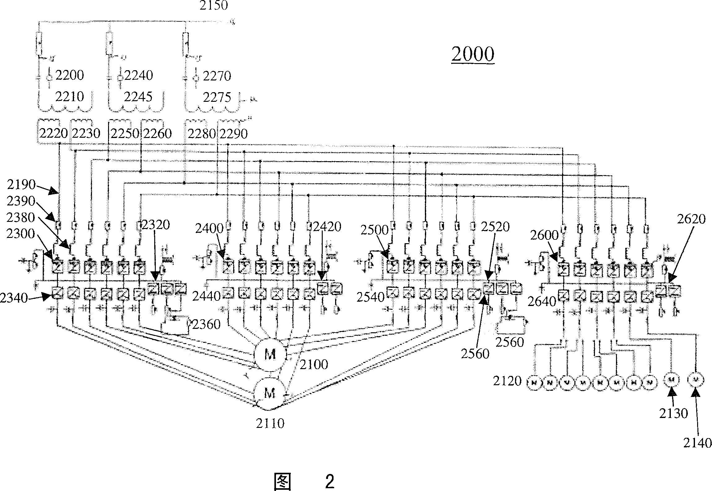
[0134] Certain exemplary embodiments may include a system including a plurality of active front-end units adapted to be electrically coupled to a direct current (DC) bus. Each of the plurality of active front end units may be adapted to be electrically coupled to an independent winding of a transformer of the plurality of transformers. Each of the plurality of active front-end units can be adapted to convert an alternating current (AC) voltage to a direct current voltage. Each of the plurality of active front end units can be adapted to supply the DC voltage to the DC bus. The DC bus may be adapted to be electrically coupled to a plurality of inverters.
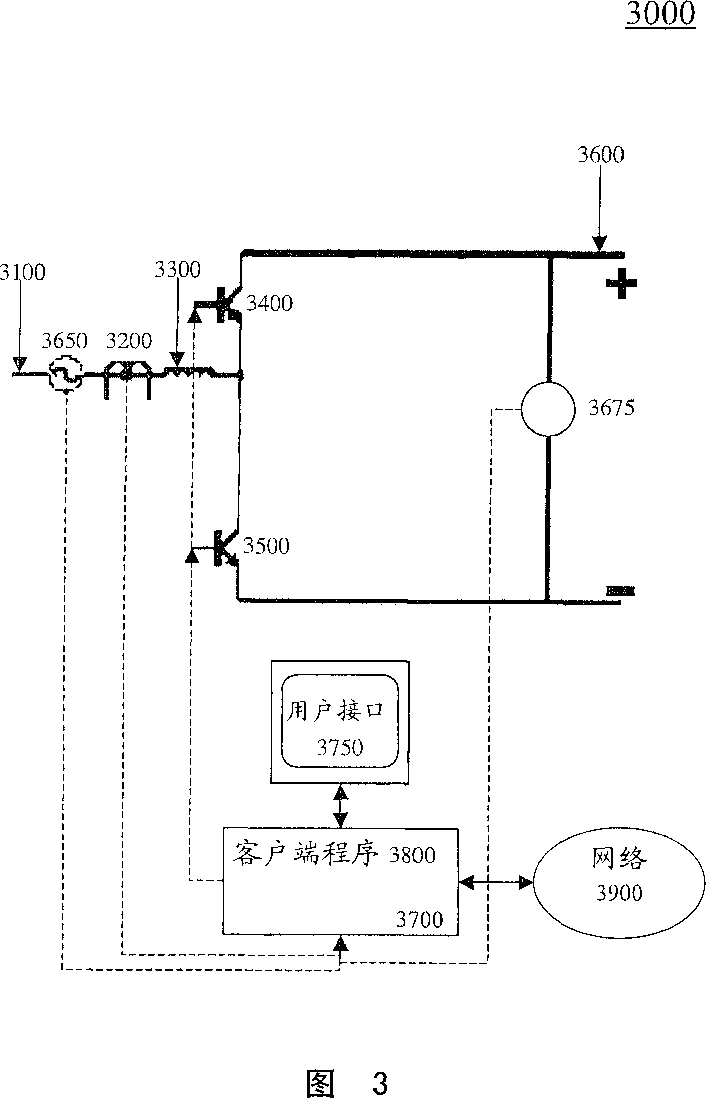
[0135] Certain exemplary embodiments may include a method for managing and / or combating harmonic distortion involved in powering an AC motor associated with a machine. The method may include, in response to a determination that the electrical variable is not within a predetermined range, automatically switching an active fr...
PUM
 Abstract
Description
Claims
Application Information
 - R&D Engineer
- R&D Manager
- IP Professional
- Industry Leading Data Capabilities
- Powerful AI technology
- Patent DNA Extraction
Browse by: Latest US Patents, China's latest patents, Technical Efficacy Thesaurus, Application Domain, Technology Topic, Popular Technical Reports.
© 2024 PatSnap. All rights reserved.Legal|Privacy policy|Modern Slavery Act Transparency Statement|Sitemap|About US| Contact US: help@patsnap.com