
Piezoelectric oscillator active valve type piezoelectric pump

A piezoelectric vibrator and active valve technology, used in pumps, machines/engines, liquid variable capacity machines, etc., can solve problems such as pump valve hysteresis, improve output performance, solve sealing difficulties, and simplify control methods.

Inactive Publication Date: 2007-10-17
JILIN UNIV
View PDF0 Cites 42 Cited by
  • Summary
  • Abstract
  • Description
  • Claims
  • Application Information

AI Technical Summary

Problems solved by technology

[0004] The invention provides a piezoelectric vibrator type active valve piezoelectric pump to solve the problem of pump valve hysteresis

Method used


Image

  • Piezoelectric oscillator active valve type piezoelectric pump
  • Piezoelectric oscillator active valve type piezoelectric pump
  • Piezoelectric oscillator active valve type piezoelectric pump

Examples


Embodiment 1

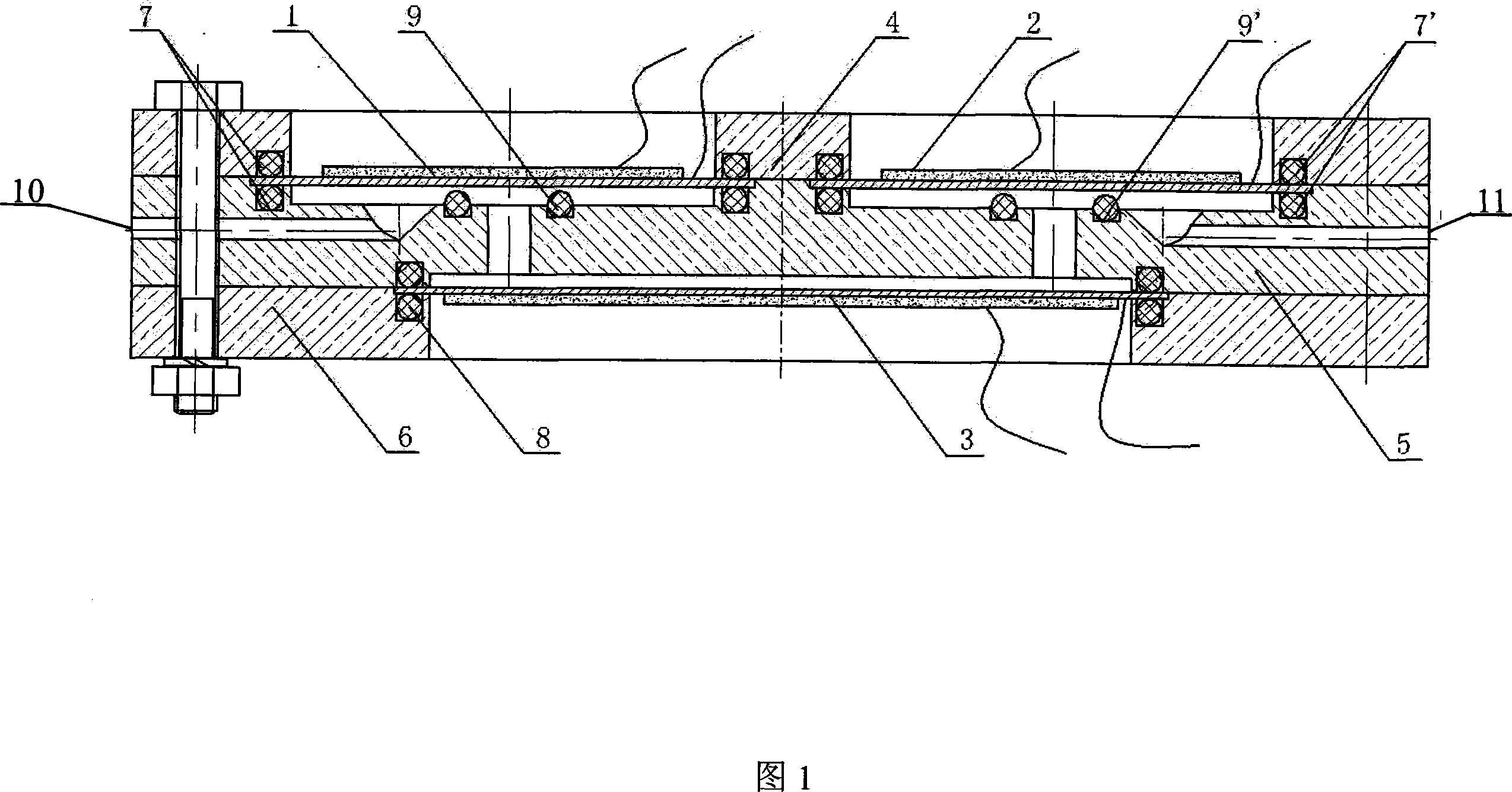
[0018] The pump body has a water inlet 10 and a water outlet 11 respectively connected to the pump chamber, the upper gland 4, the pump body 5 and the lower gland 6 are fixedly connected, and the edge of the inlet valve driving vibrator 1 is connected to the pump body through a flexible sealing ring 7 , the edge of the outlet valve driving vibrator 2 is connected to the pump body through a flexible sealing ring 7 ′, the valve port flexible ring 9 is fixed around the valve port, and the edge of the pump chamber driving vibrator 3 is fixedly connected to the pump body through a flexible material sealing ring 8 .

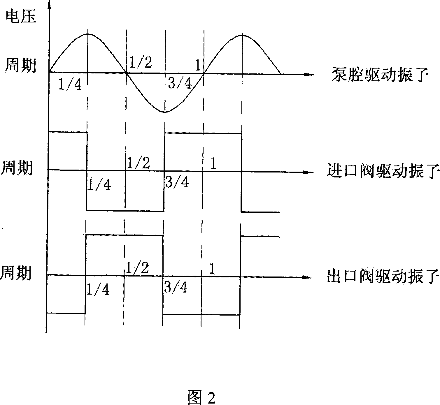
[0019] Referring to Fig. 1, the upper gland 4, the pump body 5 and the lower gland 6 are made of plexiglass as the body of the piezoelectric pump; the inlet and outlet valves 1 and 2 are respectively composed of piezoelectric vibrators, the upper gland 4 and the pump The body 5 constitutes the inlet and outlet valves. In order to make the driving piezoelectric vibrator ...

Embodiment 2

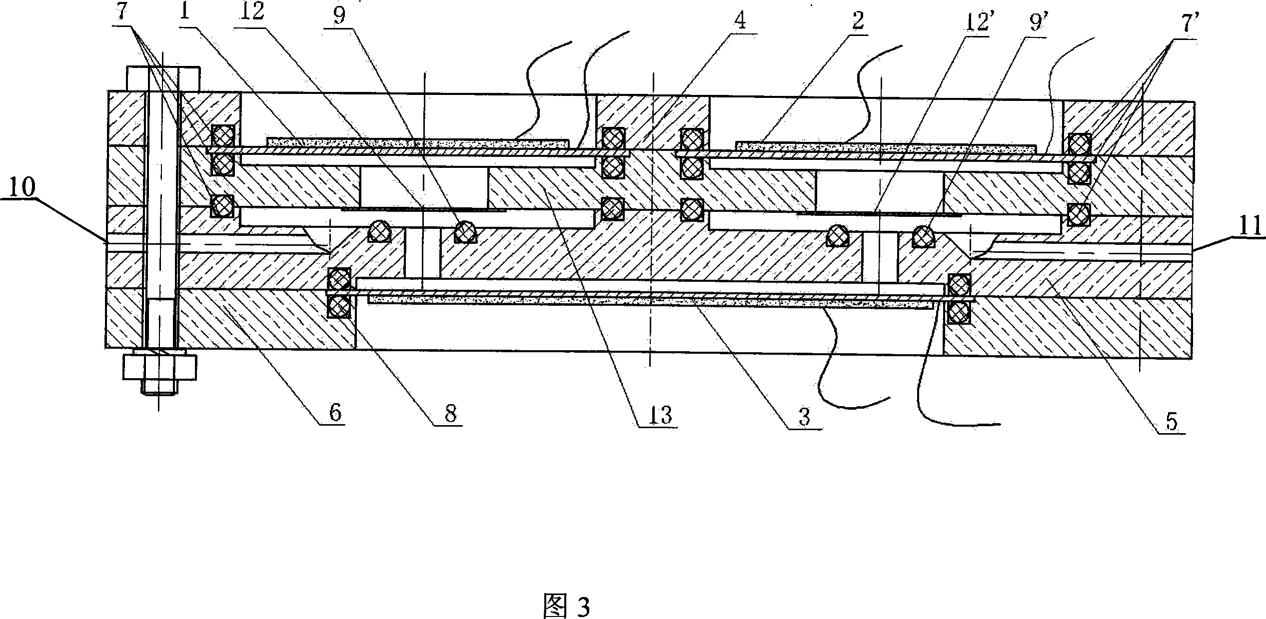
[0027] The pump body has a water inlet 10 and a water outlet 11 respectively connected to the pump chamber, the upper gland 4, the pump body 5 and the lower gland 6 are fixedly connected, and the edge of the inlet valve driving vibrator 1 is connected to the pump body through a flexible sealing ring 7 , the edge of the outlet valve drive vibrator 2 is connected to the pump body through a flexible material sealing ring 7', the valve port flexible ring 9 is fixed around the valve port inside the pump body, and the edge of the pump cavity driving vibrator 3 is connected to the pump body through a flexible material sealing ring 8' The body is fixedly connected, and a valve body 13 and a valve membrane 12 are added between the upper gland 4 and the pump body 5, and the two are fixedly connected with the valve body respectively.

[0028] Referring to FIG. 3 , compared with Example 1, the body of the piezoelectric pump has a valve membrane 12 and a valve body 13 added. The inlet and ...


PUM


Abstract

The present invention relates to a piezoelectric vibrator active valve type piezoelectric pump which belongs to micro electromechanical liquid field. The invention uses three piezoelectric vibrators, the pump body has a water intake and a water discharging port that respectively connected with the pump chamber, a top press cover, the pump body and a lower press cover are interconnected, an inlet valve and an outlet valve drive the edge of piezoelectric vibrator connect with the pump body by a flexible material sealing ring, a valve port flexible ring is fixed on the periphery of the valve port, the pump chamber drives the drive the edge of piezoelectric vibrator connect with the pump body by a flexible material sealing ring. The advantages of the pump are that it can change the mode that the inlet and outlet valves of conventional piezoelectric pump is passive in opening and closing, and it adopts active mode to control the opening and closing of the piezoelectric pump valves, reduces the lag performance for the opening and closing of the pump valves, thereby improves and advances the output property for the piezoelectric pump, and realizes the change for the pumping direction by adjusting the phase of the control signals.

Description

technical field [0001] The invention belongs to the field of micro-electromechanical fluids, and relates to changes in the mechanical structure and control mode of piezoelectric pump valves. Background technique [0002] At the end of the 1970s, research work on piezoelectric pumps has been carried out abroad. In 1978, Japanese scholar Tetsuji Tarazaki proposed the piezoelectric pump. Its main components are a bidirectionally bendable piezoelectric vibrator and a pair of mechanical one-way valves, which can realize continuous directional delivery of fluid during operation. The one-way valve can prevent the fluid from flowing backward, which can enable the piezoelectric pump to obtain higher output pressure and flow. However, since the piezoelectric vibrator in the piezoelectric pump works, the change in the volume of the pump chamber is limited, so it is necessary to increase the pump output flow by increasing the vibration frequency of the piezoelectric vibrator. However,...

Claims


Application Information

Patent Timeline
IPC IPC(8): F04B43/04
Inventor 程光明李鹏董景石吴迪曾平赵建林田萃吕刚
Owner JILIN UNIV
Learn More