
Small size self-walking type vibration compaction roller

A vibratory compaction, self-propelled technology, applied in the protection of roads and soils, road repair, etc., can solve the problems of low compaction efficiency, high cost, high noise, etc., to achieve stable walking speed, high compaction efficiency, structural high intensity effect

Inactive Publication Date: 2007-10-17
XI'AN UNIVERSITY OF ARCHITECTURE AND TECHNOLOGY
View PDF0 Cites 5 Cited by
  • Summary
  • Abstract
  • Description
  • Claims
  • Application Information

AI Technical Summary

Problems solved by technology

[0002] At present, in the compaction of house foundations and in the construction of earthworks in narrow areas such as curbs and trenches, small-scale vibratory compaction equipment such as frog compactors, electric compactors, and vibratory plate compactors are still widely used. Restricted by its working principle and structural characteristics, its forward speed cannot be adjusted according to the thickness of the medium to be pressed, the number of compaction times and other working conditions during the construction process, so the compaction efficiency is low, and some are noisy, and the machine is easily damaged. , poor safety performance, some have high cost, it is not easy to turn around when working, and the scope of application is small

Method used


Image

  • Small size self-walking type vibration compaction roller
  • Small size self-walking type vibration compaction roller

Examples


Embodiment

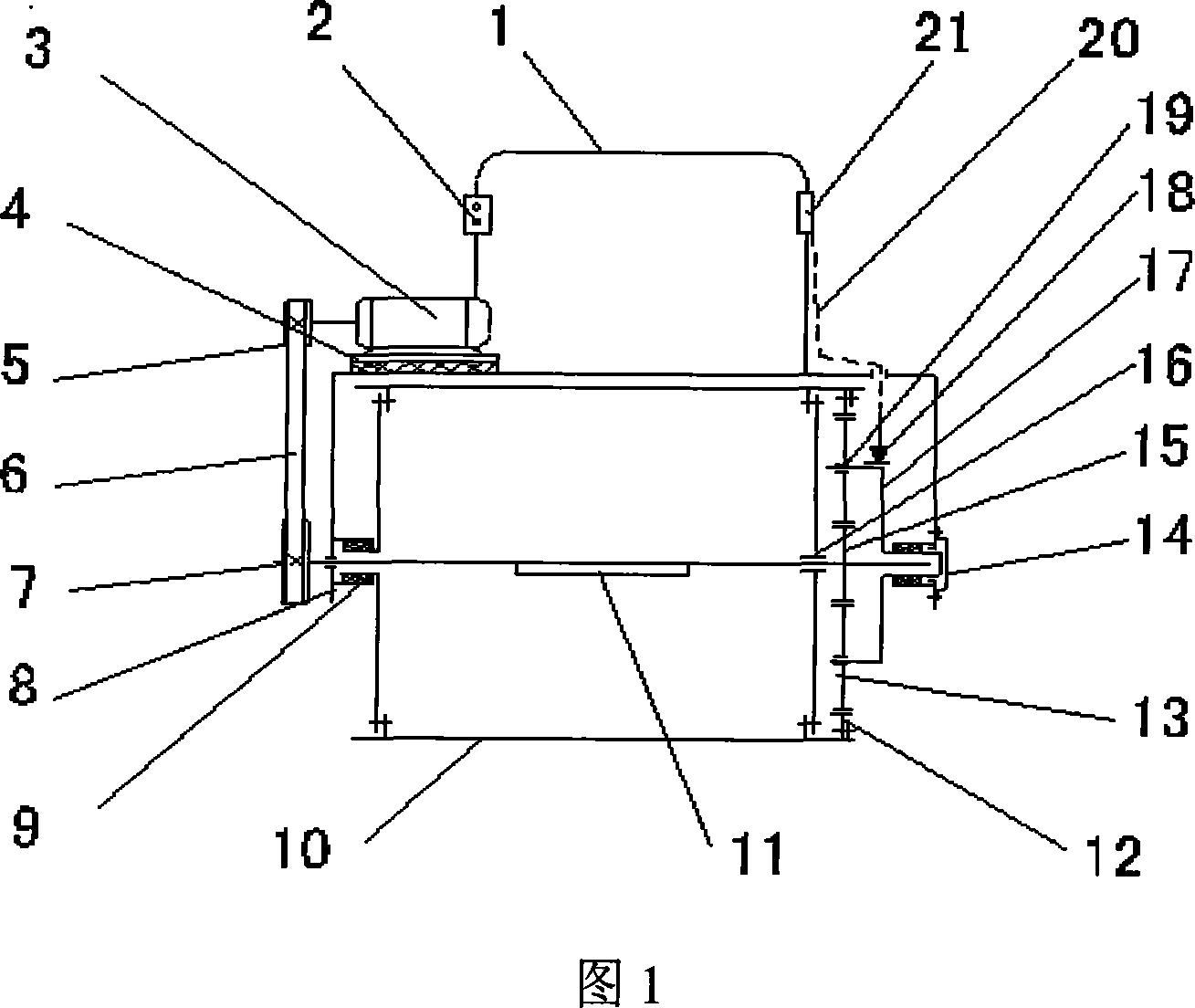
[0024] Embodiments of the present invention will be described below in conjunction with accompanying drawing 1 .

[0025] During specific construction, first transfer the compacting roller to the work site, the operator holds the handrail 1 with both hands, and then turns on the power switch 2, at this time the power on the motor 2 is transmitted through the belt transmission mechanism (5, 6, 7) To the eccentric shaft 11, the exciting force generated by the rotation of the eccentric shaft 11 is transmitted to the roller 10 through the slewing bearings 16 at both ends of the eccentric shaft 11 and the roller 10, so as to be loaded on the compacted medium. Simultaneously by manipulating the brake handle 21 to make the brake 18 brake the tie rod 17, then the intermediate gear 13 is equivalent to an idler wheel at this time, so the power is provided by the main gear 15, the intermediate gear 13 and the ring gear fixedly connected on the eccentric shaft 11. 12 is transmitted to the...

Embodiment 2

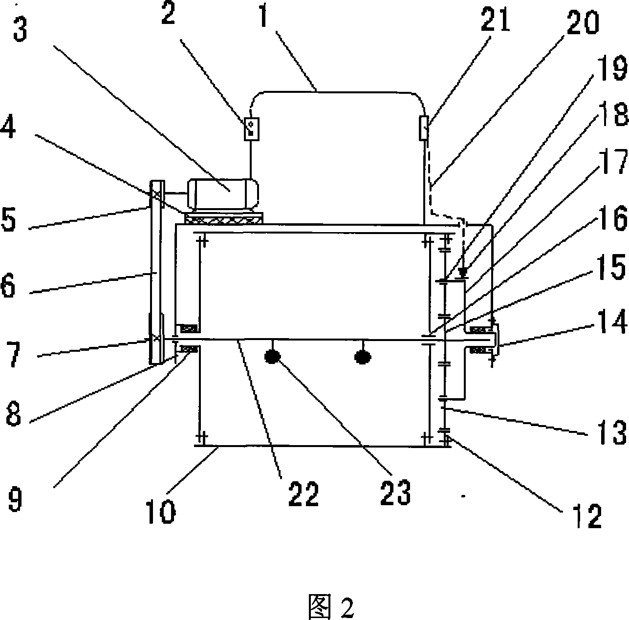
[0028] The working principle of embodiment 2 is basically the same as that of embodiment 1, except that the eccentric shaft 11 in embodiment 1 (see FIG. 1 ) is replaced by two eccentric blocks 23 (see FIG. 2 ) consolidated on a transmission shaft 22 .


PUM


Abstract

The invention discloses a minitype proper motion type vibrational compressing roll, including a drum (10), a drive mechanism. The drum (10) is provided with an eccentric shaft (11) or fixedly connected with two transmission shafts (22) of the eccentric block (23), characterized in that, the two ends of the eccentric shaft (11) or the transmission shafts (22) are installed on the turning bear (16), and the eccentric shaft (11) is fixed with a master gear (15), wherein the master gear (15), the middle gear (13) and the ring gear (12) compose a tooth gear. The middle gear (13) is connected on the tie bar (17) by a turning pair, and the ring gear (12) is fixedly connected with the drum (10), wherein the eccentric shaft (11) and the transmission shafts (22) are connected with the drive mechanism. When the compressing roll is working, the compressing roll can process the vibrating compaction and advance. The invention has small mechanical noise, stable and safe operation, high compressing efficiency, wide compressing range.

Description

technical field [0001] The invention relates to a vibrating compacting roller, in particular to a small self-propelled vibrating compacting roller, which is used for building, road and other constructions. Background technique [0002] At present, in the compaction of house foundations and in the construction of earthworks in narrow areas such as curbs and trenches, small-scale vibratory compaction equipment such as frog compactors, electric compactors, and vibratory plate compactors are still widely used. Restricted by its working principle and structural characteristics, its forward speed cannot be adjusted according to the thickness of the medium to be pressed, the number of compaction times and other working conditions during the construction process, so the compaction efficiency is low, and some are noisy, and the machine is easily damaged. , Poor safety performance, some with higher cost, not easy to turn around when working, and the scope of application is small. Co...

Claims


Application Information

Patent Timeline
IPC IPC(8): E01C19/38E02D3/046
Inventor 段志善贺利乐
Owner XI'AN UNIVERSITY OF ARCHITECTURE AND TECHNOLOGY
Learn More