Coupled methane tank
A biogas tank and conjoined technology, which is applied in the fields of biogas generation devices and sewage treatment, can solve the problems of high cost, difficulty in deep excavation, and inability to meet the needs of farmers for biogas, and achieve the effects of efficient fermentation, heat preservation, and efficiency assurance.
- Summary
- Abstract
- Description
- Claims
- Application Information
AI Technical Summary
Problems solved by technology
Method used
Image
Examples
Embodiment 1
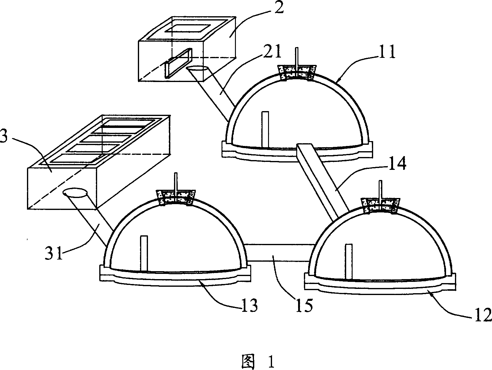
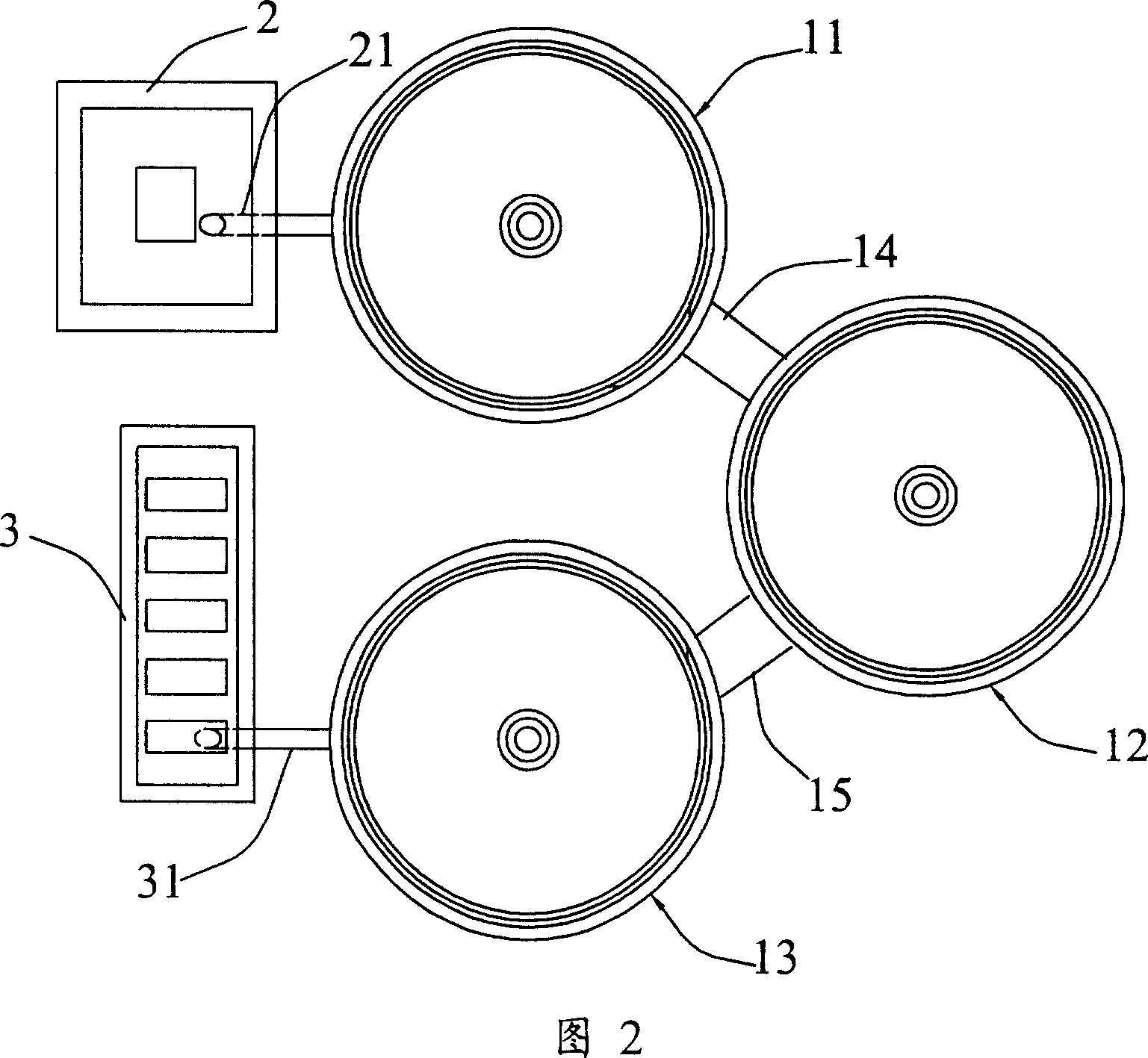
[0039] This embodiment is a biogas digester with three pools in series structure, and the structure mainly includes a feed tank 2, a first fermentation tank 11 connected to the feed tank 2 through a feed pipe 21, a second fermentation tank 12, a third fermentation tank 13, and The third fermentation tank 13 is connected to the discharge tank 3 through a discharge pipe 31 , and the second fermentation tank 12 communicates with the first fermentation tank 11 and the third fermentation tank 13 through communication pipes 14 and 15 respectively. The arrangement structure of each structure of the biogas digester is shown in Figure 2, and the three fermentation ponds are arranged in a triangle to save land space.
[0040] The detailed internal structure and size of the biogas digester are shown in Figure 3. For the convenience of illustration, the three fermentation tanks are arranged in a straight line in Figure 3, and the feed tank 2 and the discharge tank 3 pass through the feed p...
Embodiment 2
[0046] As shown in Figure 6, a biogas digester with four tanks connected in series consists of a feed tank 2, a first fermentation tank 11, a second fermentation tank 12, a third fermentation tank 13, a fourth fermentation tank 4 and a discharge tank 3 Composed in series, the internal structure and working principle of its fermentation tank are basically the same as in Example 1. Compared with Example 1, this example has a larger capacity, and the fermentation feed liquid undergoes a longer reaction in the biogas digester, and the degree of degradation is more sufficient.
Embodiment 3
[0048] This embodiment is further improved on the basis of embodiment 2, and a special gas storage device is also provided. The gas storage device is composed of two gas storage tanks 51 and 52 connected at the bottom with the same structure as the biogas tank, and two hydraulic tanks 53 respectively connected with the gas storage tanks 52 . The tops of the gas storage tanks 51, 52 communicate with the gas storage ports on the tops of the respective fermentation tanks through pipelines 55, 56. During use, a certain amount of water is put into the hydraulic pool 53, and when the biogas chamber is formed on the top of the fermentation tank, the air pressure generated by the chamber will transport the biogas to the gas storage pools 51, 52 through the pipelines 55, 56 to form the same biogas chamber. Air chamber. The air chambers in the gas storage pools 51 and 52 form a certain pressure, which makes the liquid level of the hydraulic pool 53 rise to form a hydraulic seal. The f...
PUM
 Abstract
Description
Claims
Application Information
 - R&D
- Intellectual Property
- Life Sciences
- Materials
- Tech Scout
- Unparalleled Data Quality
- Higher Quality Content
- 60% Fewer Hallucinations
Browse by: Latest US Patents, China's latest patents, Technical Efficacy Thesaurus, Application Domain, Technology Topic, Popular Technical Reports.
© 2025 PatSnap. All rights reserved.Legal|Privacy policy|Modern Slavery Act Transparency Statement|Sitemap|About US| Contact US: help@patsnap.com


