
Safety excess flow valve for gas conduits

A gas pipeline, automatic closing technology, used in safety valves, pipe components, valve details, etc., can solve problems such as expensive, and achieve the effect of increasing distance and accurate guidance

Inactive Publication Date: 2007-09-26
INTERFORGE KLEE
View PDF2 Cites 2 Cited by
  • Summary
  • Abstract
  • Description
  • Claims
  • Application Information

AI Technical Summary

Problems solved by technology

Although the construction proposed by DE 103 53 372 A1 is clearly much more compact, assembly entails certain costs due to the need to handle very delicate parts especially in relation to the magnetic device
Additionally, ring magnets imply expensive, specialized structural

Method used


Image

  • Safety excess flow valve for gas conduits
  • Safety excess flow valve for gas conduits
  • Safety excess flow valve for gas conduits

Examples


Embodiment Construction

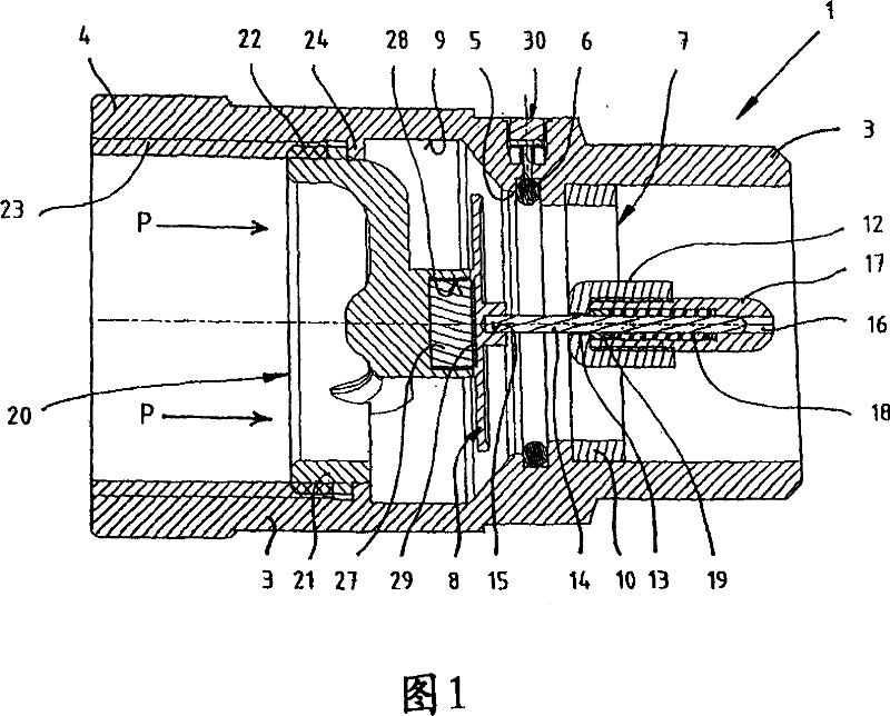
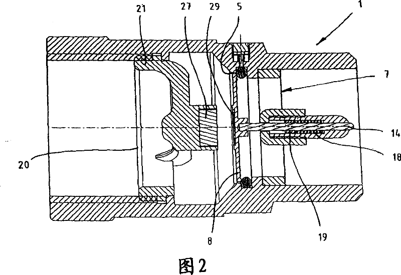
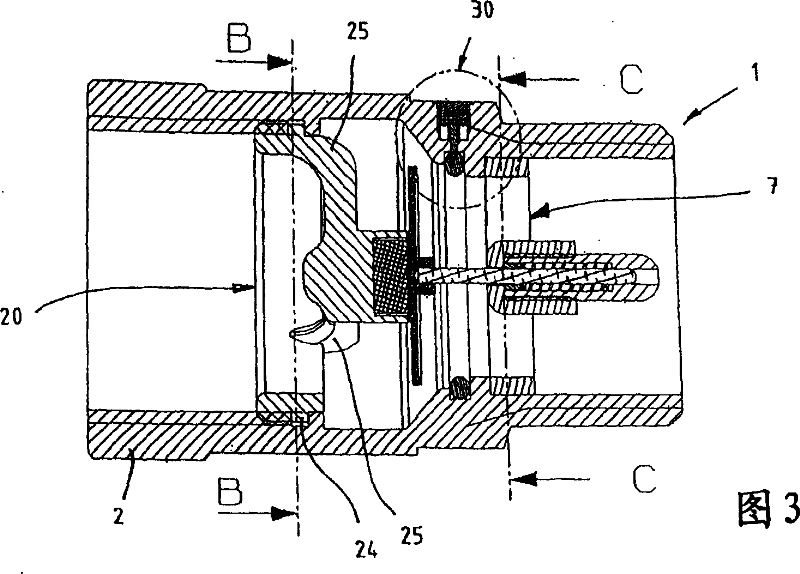
[0020] Figure 1 depicts a safety valve 1 arranged to be screwed into a gas line. For this purpose, the safety valve 1 is provided at its ends with a housing 2 of threaded connections 3 , 4 . The flow direction of the gas is indicated by arrow P. Inside the housing 2 is arranged a valve seat 5 with a sealing ring 6 which is inserted in a circumferential groove of the housing 2 . A guide bridge 7 is inserted into the housing 2 in the flow direction behind the valve seat 5 , which guide bridge 7 guides a closing body 8 which can be displaced relative to the guide bridge 7 . The closing body 8 can be moved in the direction of the valve seat 5 and can close the gas line when the maximum flow rate is exceeded. The closure body 8 shown in FIG. 1 is in the open position. The closure body 8 shown in FIG. 2 is in the closed position. If the closing body 8 is in the open position, gas can flow around the closing body 8 so that the gas can pass the valve seat 5 . If the fluid flow ex...


PUM


Abstract

Safety valve comprises a closing body (8) held in the open position by a magnetic force on a fixing bridge spaced by a guiding bridge (7). An anchor plate (29) is arranged on the closing body and is attracted by a cylindrical magnetic unit (27) placed on the fixing bridge. A restoring force is applied by a spring (18) surrounded by a guiding bolt (14). Preferred Features: A restoring force is applied by the magnetic unit. The guiding bolt is surrounded by a guiding sleeve (17) connected to the guiding bridge.

Description

technical field [0001] The invention relates to a safety valve for automatically closing a line through which fluid flows, according to the features of the preamble of claim 1 . Background technique [0002] This so-called flow monitor disclosed in DE 103 52 372 A1 is considered to be prior art. When the fluid flow exceeds the allowable maximum flow, the closing body in the flow monitor is moved against the valve seat to automatically close the gas line in the event of a leak. DE 103 52 372 A1 proposes to hold the closing body against the holding bridge by means of a magnetic force generated by magnetic means. This avoids vibrations in the closed body caused by fluctuations in the fluid flow. The magnetic means should be arranged in particular in the form of a ring, which is passed through by a central guide bolt. Although the construction proposed by DE 103 53372 A1 is significantly more compact, the assembly entails certain costs due to the need to handle very delicate ...

Claims


Application Information

Patent Timeline
Patent Type & Authority Applications(China)
IPC IPC(8): F16K17/20
CPCF16K31/084F16K17/28F16L55/1022
Inventor K·科利
Owner INTERFORGE KLEE
Learn More