Method, system and client equipment for obtaining optical fiber signal flow information of optical network

A technology of signal flow and signal flow graph, applied in the field of optical communication, can solve problems such as inability to display optical fiber connections, lower maintenance efficiency, inability to maintain single boards and/or optical fibers, etc., and achieve the effect of improving maintenance efficiency and quick management

Inactive Publication Date: 2011-09-14
HUAWEI TECH CO LTD
View PDF0 Cites 2 Cited by
  • Summary
  • Abstract
  • Description
  • Claims
  • Application Information

AI Technical Summary

Problems solved by technology

[0004] In the prior art, the graphical view of the optical network element optical fiber signal flow graph graphical system can only display the optical fiber connections between the wave subracks, but cannot display the single boards inside the wave subracks and the optical fiber connections between the boards. It is impossible to obtain the signal flow information of the optical fiber connection inside the subrack, which leads to inconvenience in the management of the optical fiber signal flow of the optical network element
Moreover, when a single board and / or an optical fiber in the wave molecular frame fails, the view of the existing optical network element optical fiber signal flow graph graphical system cannot display the failure of the single board and / or optical fiber in the wave molecular frame information, it is impossible to obtain the information of the optical fiber signal flow inside the wave molecular frame, and it is impossible to maintain the single board and / or optical fiber inside the wave molecular frame through the information displayed in the view, which makes the maintenance of the optical fiber signal flow of the optical network element inconvenient , the maintenance efficiency is reduced

Method used


Image

  • Method, system and client equipment for obtaining optical fiber signal flow information of optical network
  • Method, system and client equipment for obtaining optical fiber signal flow information of optical network
  • Method, system and client equipment for obtaining optical fiber signal flow information of optical network

Examples


Embodiment Construction

[0027] In order to make the purpose, technical solutions and advantages of the embodiments of the present invention more clear, the embodiments of the present invention will be further described in detail below in conjunction with the embodiments and the accompanying drawings. Here, the exemplary embodiments and descriptions of the present invention are used to explain the present invention, but not to limit the present invention.

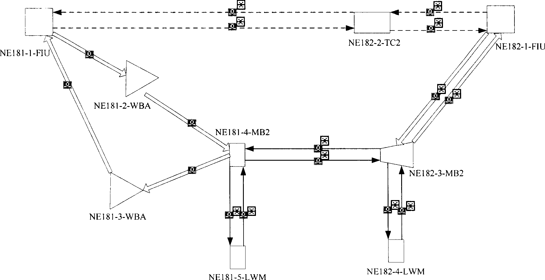
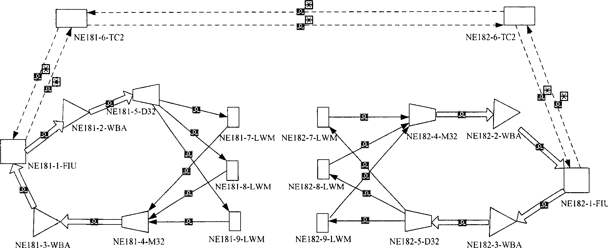
[0028] see figure 1 , which is a flowchart of a method for obtaining optical fiber signal flow information of an optical network element according to an embodiment of the present invention, the method includes the following steps:

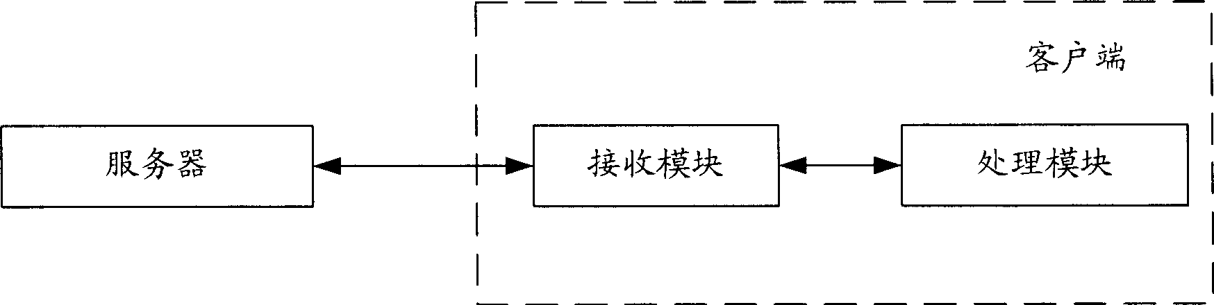
[0029] Step 101, the client obtains single board data and optical fiber data in the optical network element from the server.

[0030] In this step, the single-board data and optical fiber data in the optical network element can be obtained from the server as needed, which can be all single-board data and optical fiber ...


PUM


Abstract

The invention discloses a method for obtaining optical network element fiber signal flow information, comprises as follow: the veneer data and fiber data in optical network element which is transmitted by a server are received; veneer object and fiber object are generated according to the veneer data and fiber data, and then the optical network element fiber signal flow graph graphical system is obtained; the information of the veneer or fiber in the optical network element is displayed via the optical network element fiber signal flow graph graphical system and the optical network element fiber signal flow is obtained. The invention also discloses a method for maintaining the optical network element fiber signal flow and a system and client device for obtaining optical network element fiber signal flow information. The invention can conveniently and rapidly manage the optical network element and improve the maintenance efficiency of the optical network element.

Description

technical field [0001] The invention relates to optical communication technology, in particular to a method, system and client equipment for obtaining optical network element optical fiber signal flow information. Background technique [0002] The optical network element usually includes multiple wave sub-frames, and optical fibers can be connected between the wave sub-frames to realize service intercommunication. Each wave subrack contains multiple single boards, and there are optical fiber connections between the single boards. The optical fiber connection between the wave molecular frame and inside the wave molecular frame is complicated, and the signal flow direction is not easy to identify. [0003] At present, the optical network element optical fiber signal flow graph graphic system is usually used to obtain the information of the optical network element optical fiber signal flow. By using the obtained optical network element fiber signal flow information, the curre...

Claims


Application Information

Patent Timeline
Patent Type & Authority Patents(China)
IPC IPC(8): H04B10/12H04J14/02H04B10/08H04B10/07H04B10/25
Inventor 倪振威
Owner HUAWEI TECH CO LTD
Why Eureka
Try Eureka