
Control circuit and method for inducting luminance variation

A technology for controlling circuit and brightness change, applied in electrical components, electronic switches, pulse technology, etc., can solve problems such as interference, influence of conductive materials, misoperation of control circuit, etc., and achieve the effect of convenient induction control process

Inactive Publication Date: 2007-09-19
深圳市晟瑞科技有限公司
View PDF0 Cites 4 Cited by
  • Summary
  • Abstract
  • Description
  • Claims
  • Application Information

AI Technical Summary

Problems solved by technology

All of the above control circuit devices have certain defects. For example, the electromagnetic induction type is greatly disturbed by magnetic materials and metal materials; the capacitance induction type is easily affected by air humidity and conductive materials; the infrared emission type is easily affected by other infrared radiation. Radiation interference; microwave induction type is easily interfered by microwaves of adjacent frequencies
[0003] If the above various inductive control circuit devices are used as a control device that is approached or touched by the human body, the control circuit will be misoperated due to interference; and when there is no light, their positions cannot be easily identified. Add a luminous body such as a light-emitting LED to indicate the position, which is inconvenient to use

Method used


Image

  • Control circuit and method for inducting luminance variation
  • Control circuit and method for inducting luminance variation
  • Control circuit and method for inducting luminance variation

Examples


Embodiment Construction

[0032] Various preferred embodiments of the present invention will be described in more detail below.

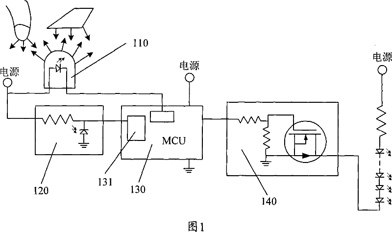
[0033] The control circuit for sensing brightness changes of the present invention, as shown in FIG. 1 , includes: an active illuminant component 110 , a brightness sensing device 120 , an arithmetic processing component 130 , and an execution component 140 . Wherein, the operation processing unit 130 is used to connect and control the entire circuit, and will send control pulses to the active luminous body 110 in a predetermined regularity, as shown in FIG. 2 . The bottom or near the position of the luminous body, in order to have a stronger induction signal.

[0034] The brightness sensing device 120 can perceive the brightness change of its installation position, and the calculation and processing part 130 performs calculation and judgment to filter out the brightness change that does not change according to the predetermined law. Therefore, by monitoring the luminance c...


PUM


Abstract

The invention discloses a control circuit which can induce the variation of the brightness as least comprises an active luminophor and a brightness induction device which are both connected with a operation processing component and are under the control of the operation processing component. The operation processing component is used to control the active luminophor to change and give out light according to the advanced law and monitor the variation of brightness with advanced law which is induced by the brightness induction device thus generating the corresponding control signal. The operation processing component is also connected with an execution component which is used to execute the manipulation action to the controlled device according to the control signal. For the reason that the control circuit and the method adopts an active luminophor component which has brightness variation according to the advanced law as if that advanced modulation is made to the detection signal, and the brightness induction device and the operation judgment of the operation processing component are combined, the invention realizes the precise, reliable and convenient induction control process in various light environments.

Description

technical field [0001] The invention relates to an induction control circuit and method, in particular to a control circuit and method for sensing brightness changes, which are used to detect and control the brightness changes when an object approaches or touches. Background technique [0002] In the control switch circuit of the prior art, common inductive switch control devices mainly include magnetic induction, capacitive induction, infrared reflection and microwave induction and so on. All of the above control circuit devices have certain defects. For example, the electromagnetic induction type is greatly disturbed by magnetic materials and metal materials; the capacitance induction type is easily affected by air humidity and conductive materials; the infrared emission type is easily affected by other infrared radiation. Radiation interference; microwave induction type is easily interfered by microwaves of adjacent frequencies. [0003] If the above various inductive co...

Claims


Application Information

Patent Timeline
IPC IPC(8): H03K17/94H03K17/968
Inventor 龚飞
Owner 深圳市晟瑞科技有限公司
Learn More