Automatically compensating clamping sealing device of glasses valve

An automatic compensation, clamping and sealing technology, used in valve devices, sliding valves, engine components, etc., can solve problems such as poor sealing, high cost, leakage, etc., to avoid rigid compression, uniform load, and prolong service life.

Inactive Publication Date: 2007-09-12
SHIJIAZHUANG NO 1 VALVE FACTORY
View PDF0 Cites 4 Cited by
  • Summary
  • Abstract
  • Description
  • Claims
  • Application Information

AI Technical Summary

Problems solved by technology

The disadvantages of the above-mentioned automatic compensation clamping and sealing device are as follows: (1) In order to avoid leakage caused by poor sealing of the neutral position between the clamping points, more clamping points are required to reduce the distance between the clamping points and the neutral position , that is: more spring cylinders are required
(2) The spring cylinder is non-standard and the cost is high

Method used


Image

  • Automatically compensating clamping sealing device of glasses valve
  • Automatically compensating clamping sealing device of glasses valve
  • Automatically compensating clamping sealing device of glasses valve

Examples


Embodiment 1

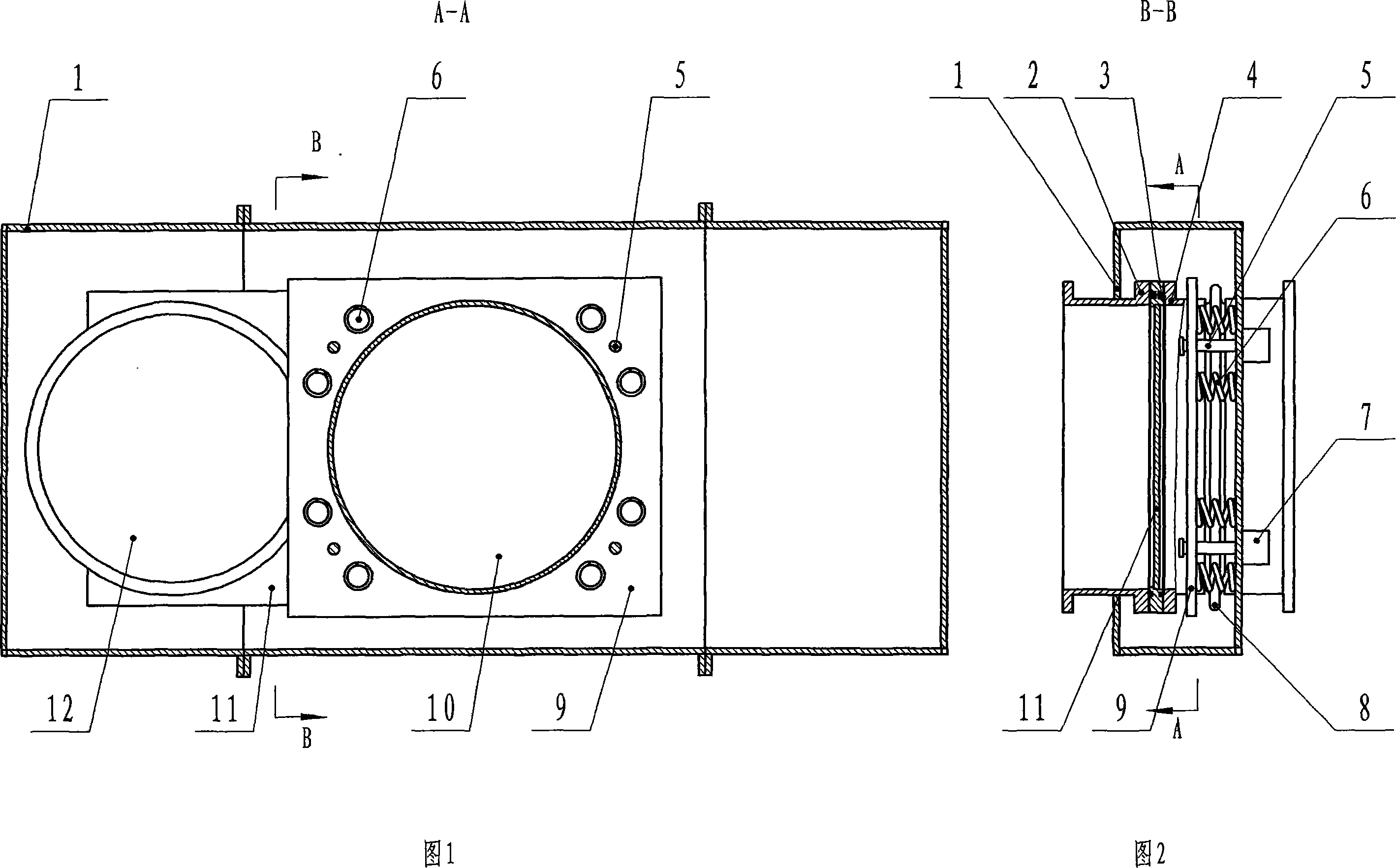
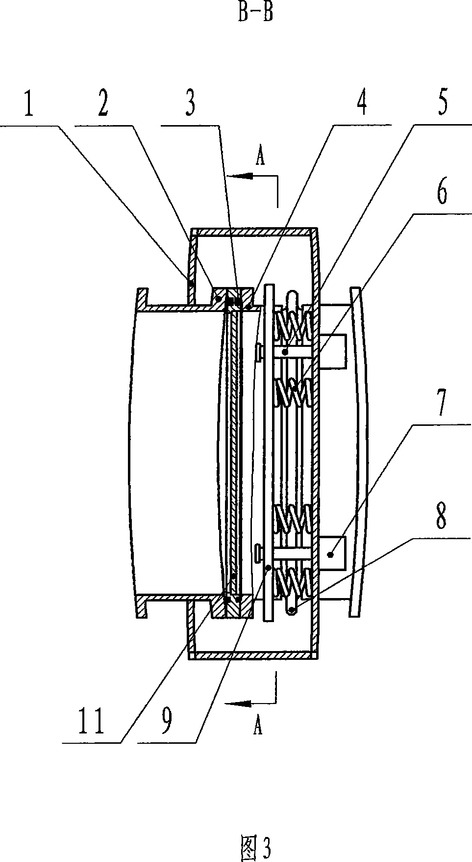
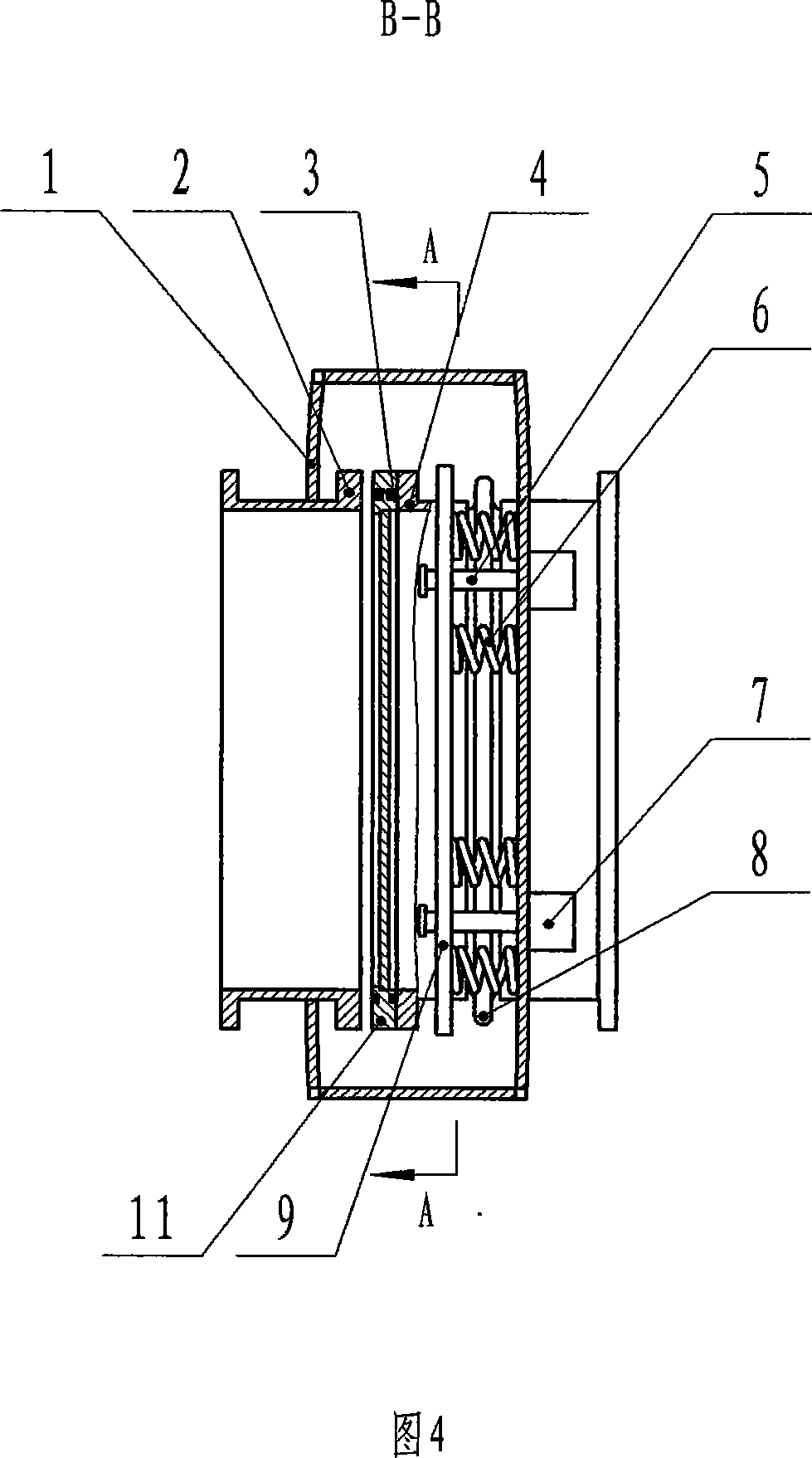
[0022] Embodiment 1 (for medium caliber glasses valve):

[0023] Embodiment 1 shown in Figures 1 and 2 is an automatic compensation clamping and sealing device used in glasses valves with medium caliber (pipe diameter φ1000-2400mm), which consists of a built-in automatic compensation clamping mechanism and a power mechanism that performs the function of pulling apart 7. Composed of pull rods 5; the built-in automatic compensation clamping mechanism is composed of clamping springs 6 biased on both sides of the longitudinal axis of the pipeline. The number of clamping springs 6 is 8, and the clamping springs 6 take the longitudinal axis of the pipeline as the symmetrical axis Symmetrical distribution; one end of the clamping spring 6 is in contact with the side wall of the movable valve seat pull plate 9, and the other end of the clamping spring 6 is in contact with the inner side wall of the valve body 1; the power mechanism 7 that performs the function of pulling apart is insta...

Embodiment 2

[0033] Embodiment 2 (for small-diameter glasses valve, the pipe diameter is φ600-700mm):

[0034] The difference between embodiment 2 and embodiment 1 is that the number of pull rods 5 is 2, and the number of clamping springs 6 is 2-4.

Embodiment 3

[0035] Embodiment 3 (for large-diameter glasses valve, the pipe diameter is φ2600-4000mm):

[0036] The difference between embodiment 3 and embodiment 1 is that the number of pull rods 5 is 8, and the number of clamping springs is 16-20.


PUM


Abstract

The invention relates a kind of auto compensation fasten device of the glass valve. It is consisted of an inside auto compensation fasten structure, a power structure and a draw link. The inside auto compensation fasten structure is consisted of the offset fasten springs at the two sides of the pipe direct-axis; one end of the fasten spring contacts with the side wall of movable valve base drawplate and the other end of it contacts with the inside wall of the valve body; the power structure is installed on the outer side of valve body; one end of the brace connects with the power output part of power structure and the other end of it goes through hole on the movable valve base drawplate; at the head of brace sets up a spacing step and the distance between the spacing step and the movable valve base drawplate is 5-15mm when the valve is opening. The favorable effectiveness of the invention is that the mount of fasten spring's add-and-subtract accords to the requirement of seal and isn't limited by the amount of brace and it can increase the mount of fasten spring singly at the state of do not increase the mount of brace in order to enhance the seal performance; and can compensate the bow distortion and gap distortion produced after the valve bearing.

Description

technical field [0001] The invention relates to an automatic compensation clamping and sealing device for a spectacle valve, which is suitable for electric and hydraulic spectacle valves and belongs to the technical field of automatic compensation clamping and sealing systems. Background technique [0002] At present, the automatic compensating clamping and sealing device of the hydraulic eyeglass valve adopts an external spring cylinder to realize compensation and sealing (see Fig. 5 and Fig. 6), and its power mechanism performs the function of pulling apart and clamping. On the valve body 1, they are evenly distributed with the center of the pipeline as the center (see Figure 5). When it is in a sealed state, when the medium pressure on the valve changes or the valve bears the external force of the pipeline, the valve body 1 will deform slightly, and the distance between the fixed valve seat 2 and the movable valve seat 4 will change, and the sp...

Claims


Application Information

Patent Timeline
Patent Type & Authority Applications(China)
IPC IPC(8): F16K3/20
Inventor 王庆芳赵军杰张庆涛曹荷涛毕相群
Owner SHIJIAZHUANG NO 1 VALVE FACTORY
Why Eureka
Try Eureka