
Ventilating device , air conditioner system, ventilating system and building

A ventilation device and air supply technology, which is applied to air conditioning systems, ventilation systems, heating and ventilation control systems, etc., and can solve problems such as increased air conditioning load and power consumption

Inactive Publication Date: 2007-09-05
MAX CO LTD
View PDF3 Cites 9 Cited by
  • Summary
  • Abstract
  • Description
  • Claims
  • Application Information

AI Technical Summary

Problems solved by technology

In this way, the temperature difference between the outside air and the indoor temperature is large, so if the ventilation is carried out frequently in summer, the indoor temperature will rise, and if the air conditioner maintains a certain temperature, the air conditioning load will increase and the power consumption will increase. will increase, this is the problem

Method used


Image

  • Ventilating device , air conditioner system, ventilating system and building
  • Ventilating device , air conditioner system, ventilating system and building
  • Ventilating device , air conditioner system, ventilating system and building

Examples


no. 8 Embodiment approach

[0768]

[0769] FIG. 21 is a configuration diagram showing an example of a ventilator 1H according to an eighth embodiment. The ventilator 1H of the eighth embodiment uses the outside air OA for the working air WA of the indirect vaporization element 11 constituting the indirect vaporization cooling unit 4 in the ventilator 1H including the dehumidification unit 33 . In addition, in the ventilator 1H of the eighth embodiment, the same reference numerals will be assigned to the same components as those of the ventilator 1G of the seventh embodiment, and will be described.

[0770] 0323

[0771] The ventilator 1H has a supply air flow path 9H that passes from the external air inlet 5 through the supply air fan 2a, the dehumidification flow path 35a of the dehumidification unit 33, and the product air flow path 11b of the indirect vaporization element 11 to the supply air outlet 6.

[0772] 0324

[0773] In addition, the ventilator 1H is provided with a branched air supply fl...


PUM


Abstract

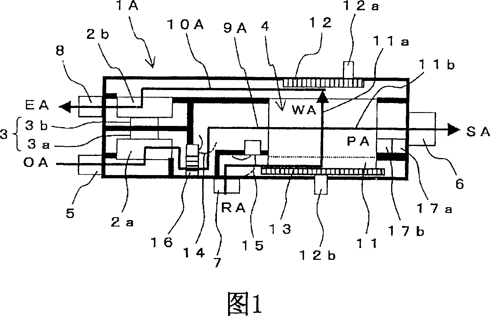
The purposes of the present invention is a ventilator having an indirect vaporizing and cooling function and a 24-hour ventilation function and installable in a housing. The ventilator (1A) comprises a supply air flow passage (9A) allowing an outside air suction port (5) to communicate with a supply air outlet port (6) through an air supply fan (2a) and the product air flow passage (11b) of an indirect vaporizing and cooling unit (4) and an exhaust gas flow passage (10A) allowing a return air suction port (7) to communicate with an exhaust gas outlet port (8) through the working air flow passage (11a) of the indirect vaporizing and cooling unit (4) and an exhaust fan (2b). The supply air flow passage (9A) comprises a supply air flow control damper (14) and an exhaust gas flow passage (10A) comprises an exhaust gas flow control damper (15). The flow rate of at least either of a working air and a product air is controlled to control a supply air temperature from the supply air outlet port (6). Also, a return air flow rate from the return air suction port (7) and a supply air flow rate from the supply air outlet port (6) are controlled so that an air in a building can be replaced in a prescribed time.

Description

technical field [0001] 0001 [0002] The present invention relates to a ventilator installed in a house to ventilate outdoors and indoors, an air-conditioning system, a ventilating system, and a building equipped with the ventilator, and particularly relates to an indirect vaporization system capable of cooling air by utilizing the heat of vaporization of water. Ventilation device with cooling function and 24-hour ventilation function. Background technique [0003] 0002 [0004] An air conditioner for cooling a space occupied by people, such as the interior of a building, has been proposed in the past. Conventional air conditioners are configured to supply cool air while circulating air in the room, and do not have a function to ventilate the room and the outside. [0005] 0003 [0006] In contrast, in recent years, due to the airtightness of houses, etc., natural ventilation has become difficult, and the time of closing the windows has become longer, and sufficient vent...

Claims


Application Information

Patent Timeline
IPC IPC(8): F24F3/147F24F11/02F24F7/08F24F1/02F24F3/16F24F13/28
Inventor 石田敏也针谷工内田晃悦小池三仁
Owner MAX CO LTD
Learn More