
Color sequential display device with back-light time delay control and its controlling method

A control method and delay control unit technology, applied to static indicators, instruments, etc., can solve problems such as uneven brightness between the upper and lower panels and scan time difference

Active Publication Date: 2007-09-05
AU OPTRONICS CORP
View PDF0 Cites 26 Cited by
  • Summary
  • Abstract
  • Description
  • Claims
  • Application Information

AI Technical Summary

Problems solved by technology

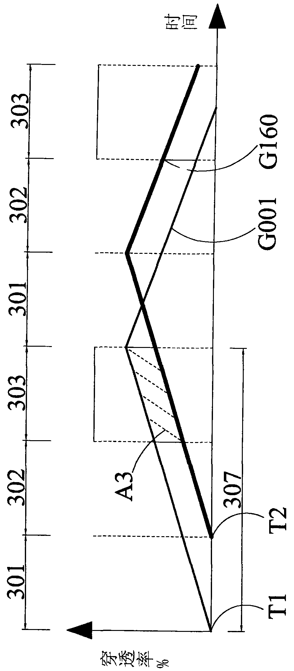
Adjust the time point when the backlight is turned off through the backlight delay control unit. For example, the time point when the backlight is turned off is about the addr

Method used


Image

  • Color sequential display device with back-light time delay control and its controlling method
  • Color sequential display device with back-light time delay control and its controlling method
  • Color sequential display device with back-light time delay control and its controlling method

Examples


Example Embodiment

Please refer to FIG. 7, which is a functional block diagram of a color sequential display with backlight time delay control according to a first preferred embodiment of the present invention. The color sequential display includes a liquid crystal panel 704, a backlight 703, a source data driving circuit 705, a gate scanning driving circuit 706, a backlight control circuit 702, and a backlight delay control unit 701. The three-primary color (RGB) backlight 703 is, for example, a light-emitting diode array (LED Array). In the three sub-frames constituting each frame, the three-primary color light sources are switched on in time sequence to enter the liquid crystal panel 704. The source data driving circuit 705 provides a data line voltage that determines the turning angle of the liquid crystal molecules. The gate scan driving circuit 706 sequentially supplies scan line voltages to the scan lines on the panel 704. The backlight control circuit 702 provides a backlight driving voltage ...


PUM


Abstract

A display of color sequence type consists of a liquid crystal face plate, a back light source, a driving circuit for generating pixel voltage to drive said liquid crystal face plate and a back light time delay control unit for delay-regulating close time point of back light source, setting said close time point in next sub-frame and using said delay close function to make liquid crystal display have excellent uniformity of picture.

Description

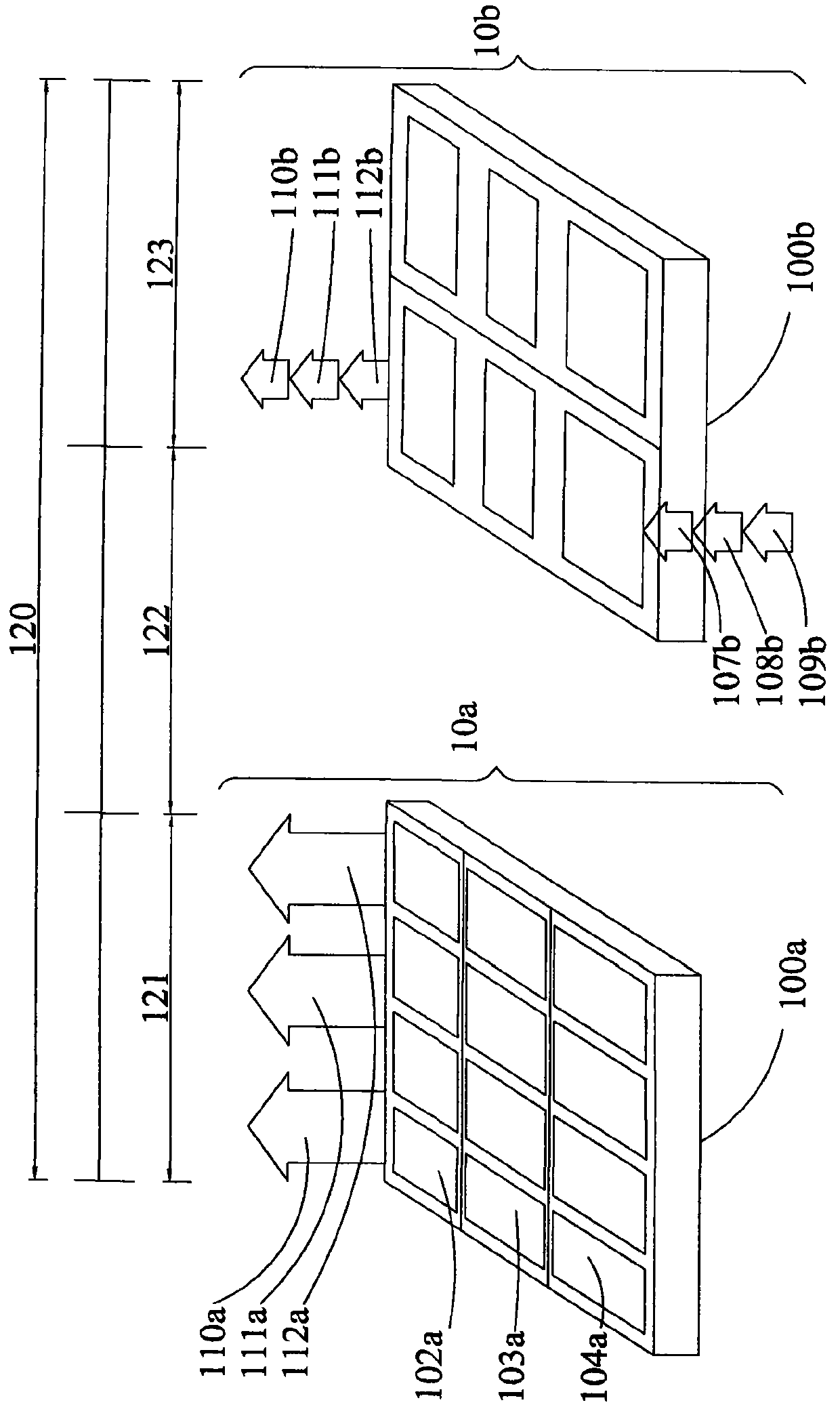
technical field The present invention relates to a liquid crystal display, in particular to a color sequential display (Color Sequential Display) with backlight time delay control and its control method. Background technique Generally, the color mixing method commonly used in liquid crystal displays can be divided into two categories. One is the spatial color mixing method such as color filter (Color Filter) technology, which mainly uses color mixing in space, because each pixel is composed of three primary colors. (RGB) sub-pixel configuration. When the sub-pixels of the three primary colors are smaller than the range that can be distinguished by human eyes, by controlling the intensity of the light passing through the sub-pixels of the three primary colors, the effect of color mixing can be obtained. For example, a conventional liquid crystal panel 10a shown in FIG. 1a uses color filter technology to form any frame 120 . Because the color filter has three primary colors...

Claims


Application Information

Patent Timeline
IPC IPC(8): G02F1/133G09G3/36G09G3/20
Inventor 黄雪瑛江明峰周玉蕙马玫生
Owner AU OPTRONICS CORP
Learn More