Scavenger fan

A technology for a ventilating fan and a metal bracket, which is applied in the field of ventilating fans, can solve the problems of deformation of the motor bracket, difficult heat dissipation structure, contact of fan blades 5, etc., and achieves the effect of improving heat dissipation and safety

Inactive Publication Date: 2007-08-29
PANASONIC ECOLOGY SYSTEMS GUANGDONG CO LTD +1
View PDF0 Cites 6 Cited by
  • Summary
  • Abstract
  • Description
  • Claims
  • Application Information

AI Technical Summary

Problems solved by technology

Although such a design reduces the weight, the long-term operation of the motor 3 will generate a lot of heat. If the heat cannot be effectively dissipated, the temperature of the motor 3 will rise, and the motor bracket 7 connected to the fixed motor 3 will be deformed. , causing the motor 3 to deviate from the original position and affect the performance of the ventilation fan. In severe cases, the fan blade 5 may touch the snail shell 2 and cause damage to the ventilation fan
However, due to the limitation of the internal space of the ventilation fan, it is very difficult to design a heat dissipation structure for the motor 3 alone

Method used


Image

  • Scavenger fan
  • Scavenger fan
  • Scavenger fan

Examples


Embodiment Construction

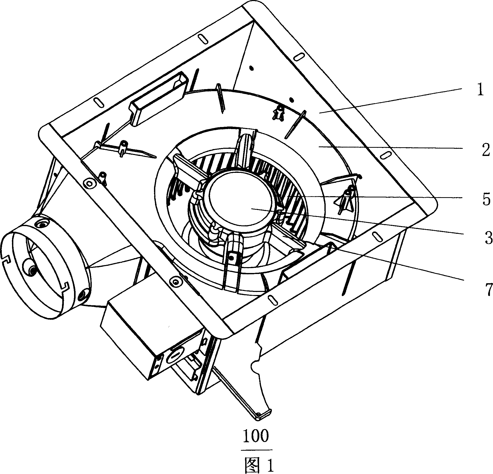
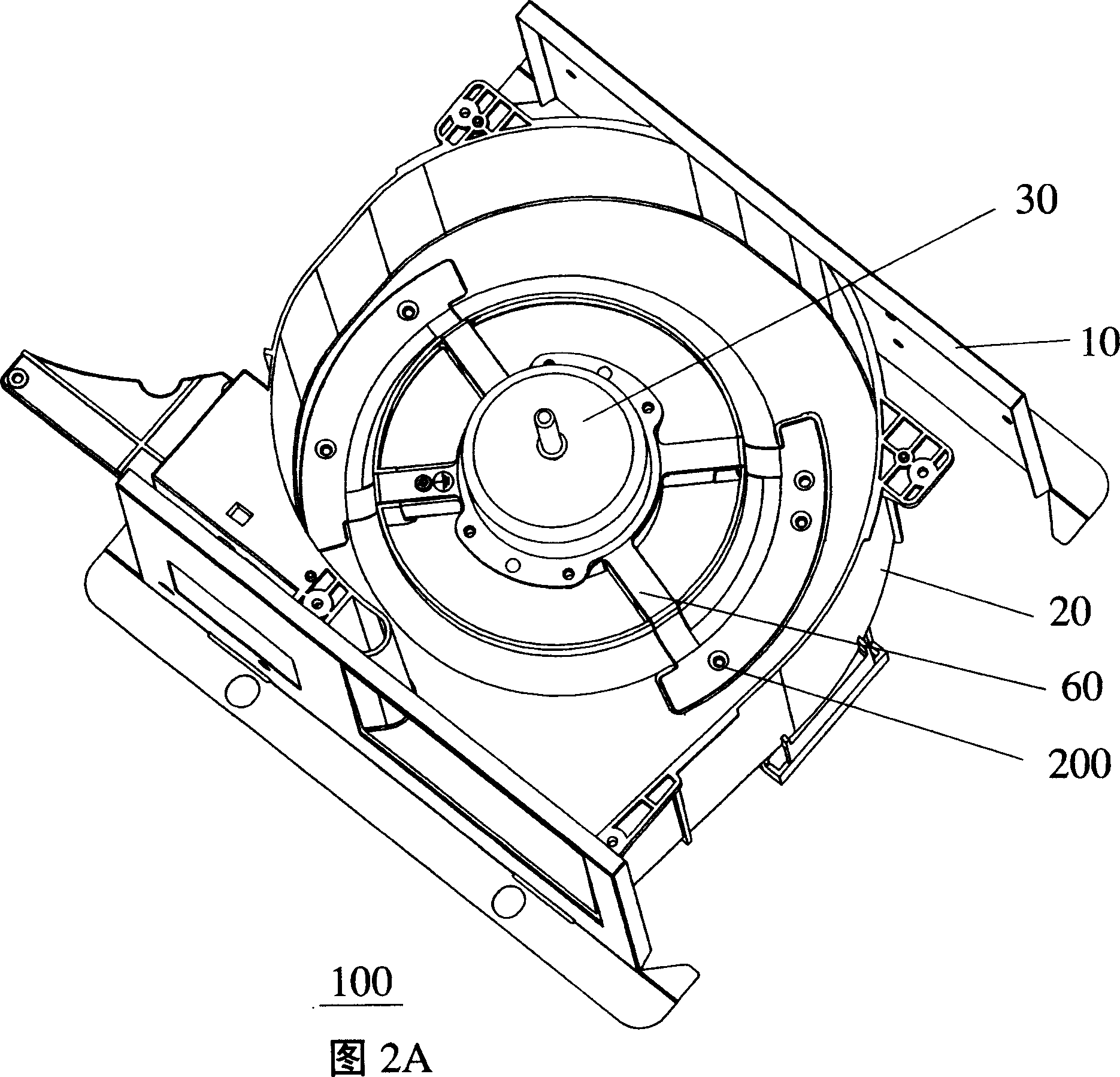
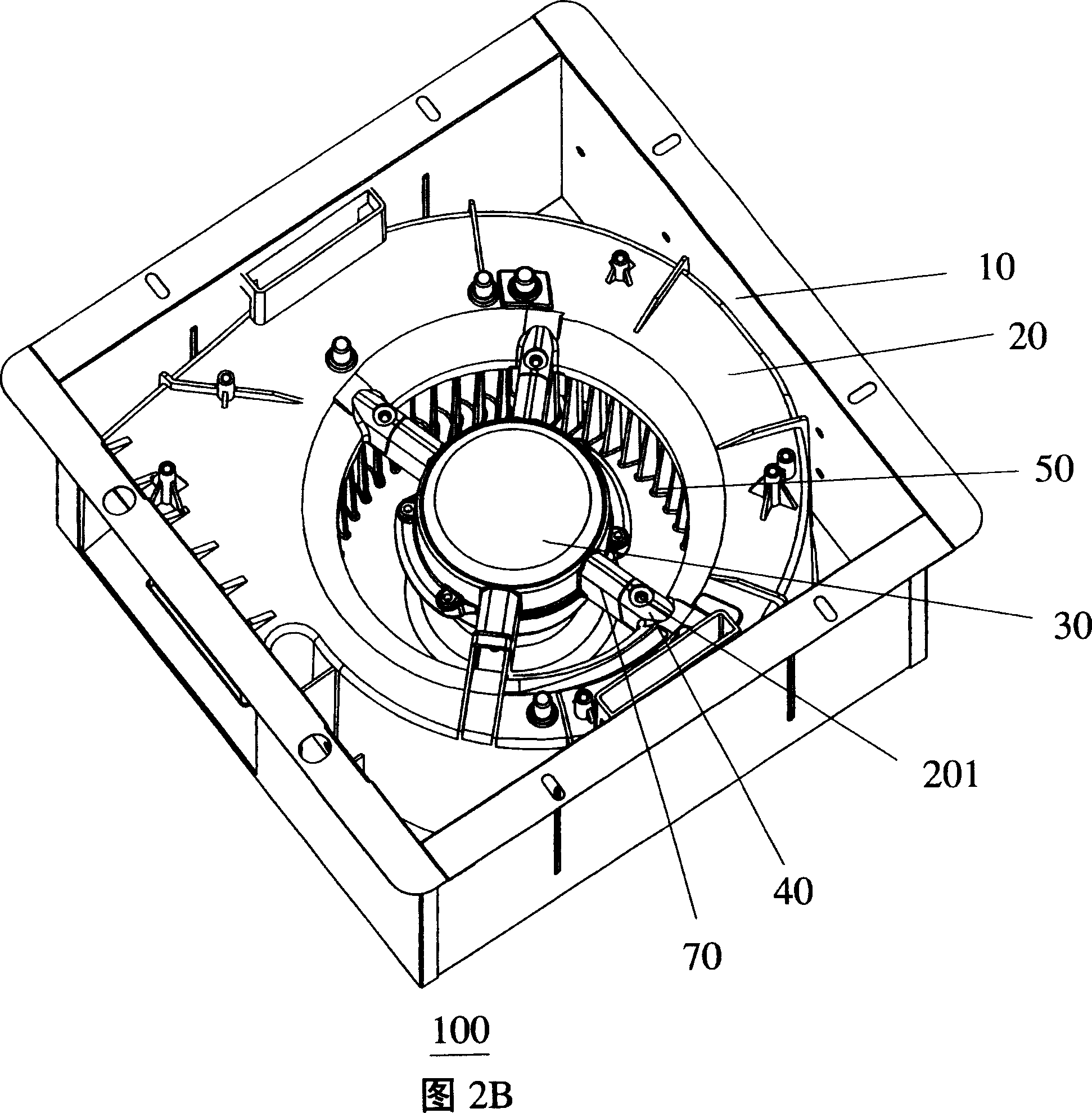
[0018] As shown in FIG. 2A and FIG. 2B , they are schematic diagrams of the front and back sides of the first embodiment of the present invention. For clarity of illustration, fan blades are removed in Fig. 2A. Ventilation fan 100 has frame 10 , snail shell 20 and motor 30 . The motor 30 is fixed on the opening in the snail shell 20 through a metal motor bracket, and the fan blade 50 is mounted on the motor 30 . It can be seen from the figure that the metal motor bracket is formed by superimposing and fixing the first metal bracket 60 and the second metal bracket 70 up and down. Compared with the known technology in FIG. 1 , the present invention changes the material of the motor bracket from resin to metal. The first metal bracket 60 and the second metal bracket 70 clamp and fix the motor together. One end of the first metal bracket 60 is fixed on the casing of the motor 30 , and the other end is finally connected into a sheet and fixed on the inner wall of the snail shell...


PUM


Abstract

The invention is a ventilator, comprising: framework, snail shell arranged in the framework, motor bracket arranged at the hatch in the snail shell, and motor arranged in the motor bracket, where the framework is of metal material, and it is characterized in that the motor bracket is of metal material. Because of good heat radiation performance and solidity, it has better safety and stability.

Description

technical field [0001] The invention relates to a ventilation fan. Background technique [0002] Ventilation fans are a common type of ventilation device, one type is mounted on the ceiling frame and is used to draw the air in the room from above the ceiling. In consideration of the safe weight of the ceiling, some measures are usually taken to reduce the weight of the ventilation fan. [0003] As shown in FIG. 1 , a ventilation fan 100 has a frame 1 , a snail shell 2 and a motor 3 installed in the frame. The motor 3 is fixed on the opening in the snail shell 2 through a motor bracket, and the fan blade 5 is mounted on the motor 3 . Negative pressure is formed in the snail shell 2 by the rotation of the fan blade 5 to extract air. Considering overall robustness, the frame 1 is usually made of metal. In order to reduce the weight, the snail shell 2 is made of resin material; the motor bracket 7 is integrally formed with the snail shell and is also made of resin material. ...

Claims


Application Information

Patent Timeline
Patent Type & Authority Applications(China)
IPC IPC(8): F04D29/02F04D29/62
CPCF04D29/4226F04D25/12F04D29/023F04D29/626F05D2230/64
Inventor 杨敬涛玄光洙饶泽伟
Owner PANASONIC ECOLOGY SYSTEMS GUANGDONG CO LTD
Why Eureka
Try Eureka