Axial flow positive displacement gas generator with combustion extending into an expansion section

A variable-capacity, axial-flow technology, used in combustion chambers, combustion equipment, combustion methods, etc., can solve the problem of not being able to have both at the same time.

Active Publication Date: 2007-08-29
GENERAL ELECTRIC CO
View PDF1 Cites 0 Cited by
  • Summary
  • Abstract
  • Description
  • Claims
  • Application Information

AI Technical Summary

Problems solved by technology

Turbomachines based on gas generators are widely used in various fields, but they cannot simultaneously have many desired characteristics, such as hig...

Method used


Image

  • Axial flow positive displacement gas generator with combustion extending into an expansion section
  • Axial flow positive displacement gas generator with combustion extending into an expansion section
  • Axial flow positive displacement gas generator with combustion extending into an expansion section

Examples


Embodiment Construction

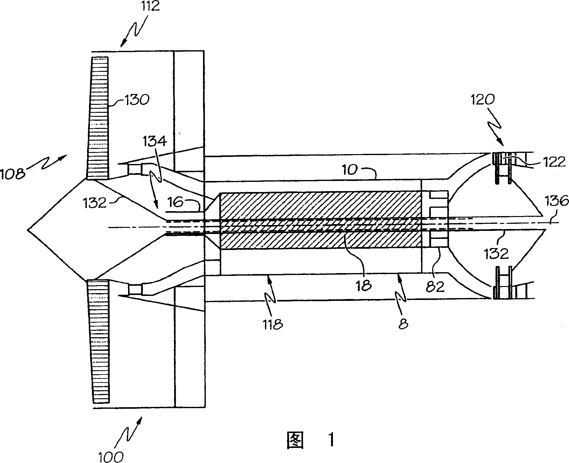
[0014] What Fig. 1 shows is an exemplary embodiment of variable displacement axial-flow engine 8, what shows here is a gas generator 10 in gas turbine engine 100 equipment, in this engine, gas generator 10 is used for The turbine is driven to do work to turn the fan 108 in the fan section of the engine 100 . The gas generator 10 can also be used to directly drive energy consumers, such as ship propulsion and generators or aircraft nozzles or fans. The exemplary embodiment of gas turbine engine 100 shown in FIG. 1 is an aircraft gas turbine engine having a core engine 118 with gas generator 10 downstream of fan section 112 . Gas is discharged from the gas generator 10 into a low pressure turbine (LPT) 120 having a row of low pressure turbine rotor blades 122 . The low pressure turbine rotor blades 122 drive a row of circumferentially spaced fan rotor blades 130 of the fan 108 connected to the fan section 112 via a low pressure shaft 132 to form a low pressure duct 134 around a...


PUM


Abstract

An axial flow positive displacement engine (8) has an inlet (20) axially spaced apart and upstream from an outlet (22). Inner and outer bodies (12, 14) have offset inner and outer axes (16, 18) extend from the inlet (20) to the outlet (22) through first, second, and third sections (24, 26, 28) in serial downstream flow relationship. At least one of the bodies is rotatable about its axis. The inner and outer bodies (12, 14) have intermeshed inner and outer helical blades (17, 27) wound about the inner and outer axes (16, 18) respectively. The inner and outer helical blades (17, 27) extend radially outwardly and inwardly respectively. The helical blades have first, second, and third twist slopes (34, 36, 38) in the first, second, and third sections (24, 26, 28) respectively. The first twist slopes (34) are less than the second twist slopes (36) and the third twist slopes (38) are greater than the second twist slopes (36). A combustion section (40) extends axially downstream from the second section (26) through at least a portion (42) of the third section (28).

Description

technical field [0001] This invention relates generally to turbomachinery and gas generators, and more particularly to variable capacity axial flow gas generators. Background technique [0002] Gas generators are used in the core of gas turbine engines, such as turbofan engines and other gas turbine engines, which have a compressor section, a combustion section and a turbine section arranged in co-flow relationship. The function of the gas generator is to provide high-energy fluid, which is used to power various equipment. Axial flow gas generators are particularly useful in many turbomachinery. Turbomachines based on gas generators are widely used in various fields, but they cannot have many desired characteristics at the same time, such as high specific energy exhaust flow (energy per unit mass), high Near steady fluid flow, reasonable thermal efficiency over a wide range of operating conditions. One goal of gas generator manufacturers is to produce gas generators that ...

Claims


Application Information

Patent Timeline
IPC IPC(8): F02C3/06
CPCF02K5/00Y02T50/671F01C11/008F05D2220/327F05D2250/25F23R3/56F01C1/107F02C5/06F05D2220/326F02C3/055F05D2260/40311Y02T50/60
Inventor K·D·默罗B·F·鲍威尔
Owner GENERAL ELECTRIC CO
Why Eureka
Try Eureka