
Automatic temperature controlling device of gas kitchen range

An automatic temperature control and gas stove technology, applied in the field of stoves, can solve the problems of affecting the normal use of gas stoves, inaccurate temperature of temperature control switches, etc., and achieve the effects of accurate detection of pot bottom temperature, simple structure, and convenient manufacture

Inactive Publication Date: 2007-08-22
WENZHOU JINGHUAN TECH CO LTD
View PDF1 Cites 9 Cited by
  • Summary
  • Abstract
  • Description
  • Claims
  • Application Information

AI Technical Summary

Problems solved by technology

In this way, the temperature detected by the temperature control switch is inaccurate, which affects the normal use of the gas stove.

Method used


Image

  • Automatic temperature controlling device of gas kitchen range
  • Automatic temperature controlling device of gas kitchen range

Examples


Embodiment 1

[0027] As shown in FIG. 1 , an air intake pipe 2 is connected to the gas cooker, and an air valve 4 and an igniter 3 are arranged on the air intake pipe 2 . Open the gas valve 4 and the gas can enter the burner 1 of the gas range through the intake pipe 2, and the gas at the burner 1 can be ignited by the igniter 3 simultaneously. The automatic temperature control device of the gas cooker is arranged at the burner 1 of the gas cooker, through which the amount of gas entering the burner 1 from the intake pipe 2 can be controlled, and finally the purpose of changing the firepower of the burner 1 can be achieved.

[0028] The automatic temperature control device of the gas cooker includes a solenoid valve 5, a control circuit and a temperature sensing probe 6. The electromagnetic valve 5 is arranged on the intake pipe 2, and the electromagnetic valve 5 is connected with the control circuit. The temperature-sensing probe 6 is connected to the control circuit. The outer side of th...

Embodiment 2

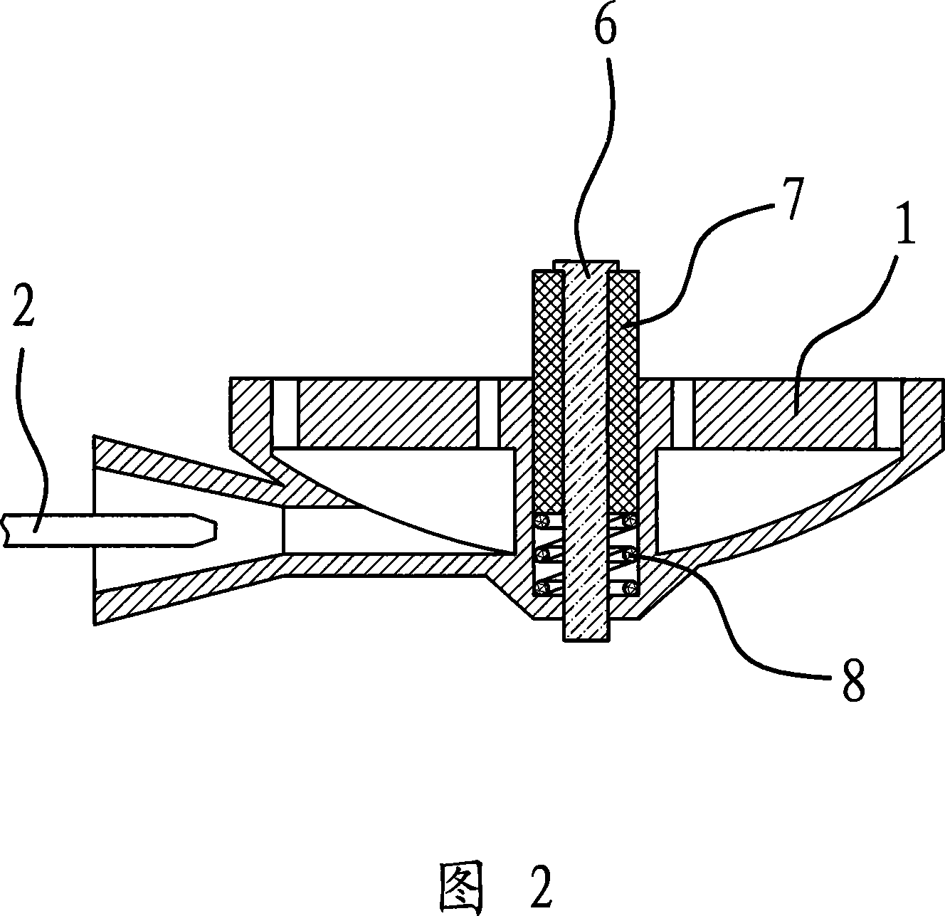
[0036] The structure and principle of this embodiment are basically the same as that of Embodiment 1. The difference is that the above-mentioned elastic mechanism is a spring 8 set on the lower part of the temperature probe 6, and the two ends of the spring 8 act on the temperature probe 6 and the burner 1 respectively. , and the above-mentioned heat-insulating sheath 7 is fixedly connected with the temperature-sensing probe 6, as shown in FIG. 2 . It can be seen that under the action of the spring 8, the heat-insulating sheath 7 and the temperature-sensing probe 6 will move upward together.


PUM


Abstract

The present invention provides an automatic temperature control device for gas range. Said automatic temperature control device is placed in the burner position of gas range, on the gas inlet tube connected with the burner an igniter and a gas valve are set. Said temperature control device includes an electromagnetic valve placed on the gas inlet tube and a control circuit; said electromagnetic valve is connected with said control circuit. In the described burner, a temperature-sensing probe connected with said control circuit is set. The outer side of said temperature-sensing probe is covered with a heat-insulating protective sleeve, the described temperature-sensing probe and heat-insulating protective sleeve can be upwards and downwards moved relatively to the burner, and on the burner a spring mechanism is set, said spring mechanism can be used for making the temperature-sensing probe and heat-insulating sleeve be upwards and downwards moved.

Description

technical field [0001] The invention belongs to the technical field of cookers, and relates to a gas cooker, in particular to an automatic temperature control device for the gas cooker. Background technique [0002] The gas stove is beautiful, durable and clean, so it is widely used as a stove. In order to control the size of the firepower in real time during the cooking process, so that the temperature is always moderate during the cooking process, an electronic temperature control device is installed at the burner. [0003] After long-term exploration and research, people have designed a variety of electronic temperature control devices, one of which is an electronic temperature measuring device connected to the handle through an electronic probe buried in the pot body, which can be intuitively adjusted and controlled. body temperature. When the firepower is too high, remove the pot from the burner, and turn the air valve at the intake pipe to reduce the intake air; when...

Claims


Application Information

Patent Timeline
IPC IPC(8): F24C3/12
Inventor 吕海洋
Owner WENZHOU JINGHUAN TECH CO LTD
Learn More