Apparatus for carrying in/out substrate and method for carrying in/out substrate
A technology of output, input, and substrate, which is applied in the direction of transportation and packaging, conveyors, conveyor objects, etc., and can solve problems such as damage, accidents, and substrate damage
- Summary
- Abstract
- Description
- Claims
- Application Information
AI Technical Summary
Problems solved by technology
Method used
Image


Examples
no. 1 approach
[0037] Hereinafter, embodiments of a substrate input / input device to which the present invention is applied will be described with reference to the drawings.
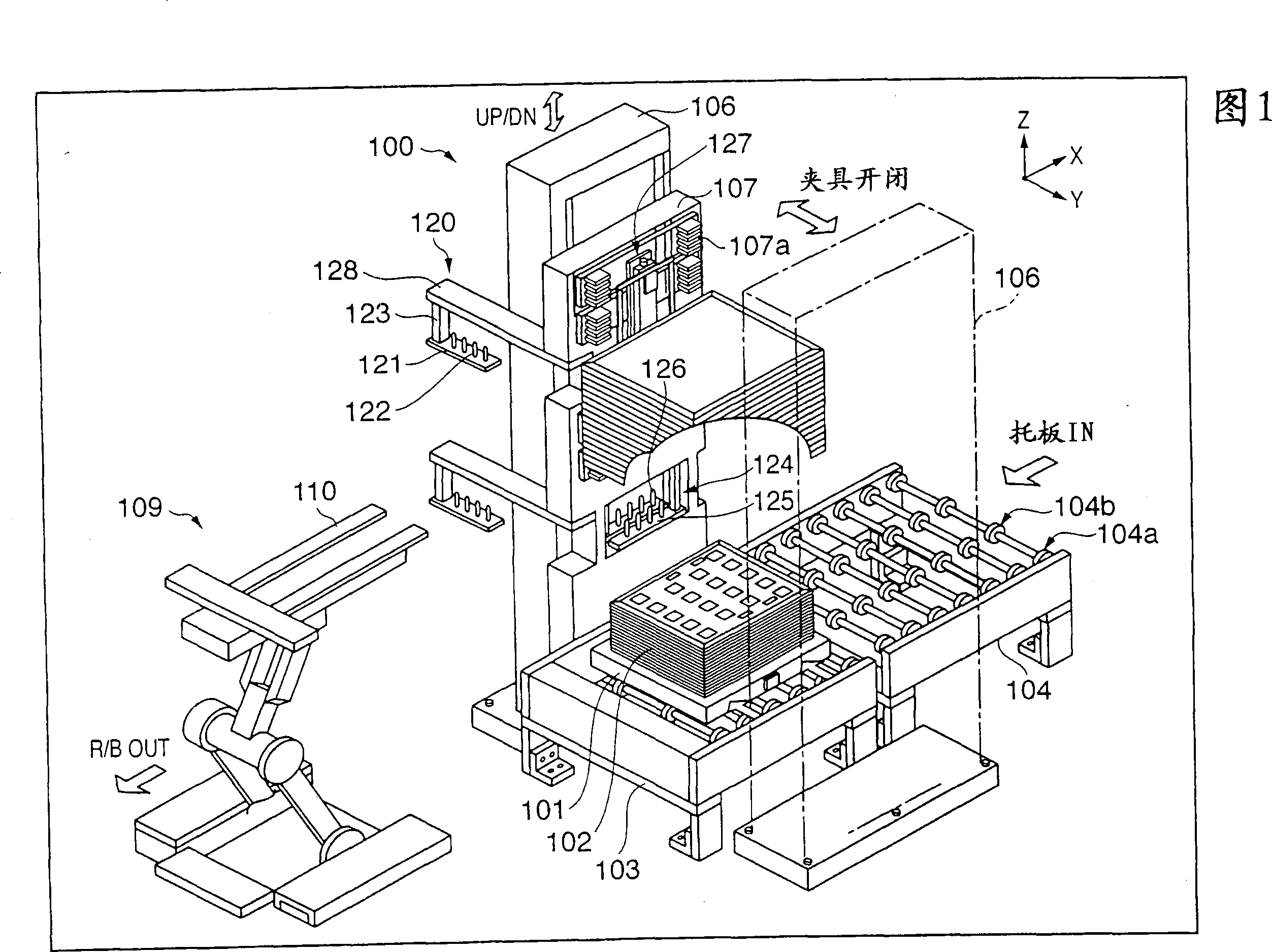
[0038] FIG. 1 is an overall appearance view showing a substrate input / output device 100 according to an embodiment of the present invention. The substrate output / input device 100 has a function of sequentially taking out glass substrates 108 (not shown in FIG. Store on a tray. Moreover, when the board|substrate exists in all trays, the glass substrate 108 is taken out sequentially from the tray of the lowest stage. Also, for example, when all the lower trays of a certain tray are empty, the glass substrate 108 may be taken out from the tray above the upper tray or loaded into the lower tray. When the glass substrates 108 are loaded on the trays of all layers, the glass substrates are taken out sequentially from the lower layer, and when the glass substrates are loaded into all the empty trays, the loading operation is...
no. 2 approach
[0135] In the above-mentioned embodiment, the following case has been described. That is, when the position of the glass substrate 108 placed on the slide pin 122 and the rotation pin 126 or the glass substrate 108 placed on the lift pin 105 is displaced, the The glass substrate 108 is adjusted by the robot 109 to solve the positional deviation, but a positioning function of the glass substrate 108 may be added to the substrate output / input device 100 .
[0136] FIG. 14 is a diagram showing a configuration example in which a positioning unit 200 is provided on a pallet clamp unit. In the example shown in the figure, the positioning unit 200 is attached via the attachment part 201 to the lower side of both ends of the rod 1002' extending the second rod 1002 of the tray clamp unit in the X direction.
[0137] The positioning assembly 200 includes: rollers 210a, 210b, 211a and 211b for positioning, a supporting plate 220 for supporting the rollers 210a, 210b, 211a and 211b, an ac...
no. 3 approach
[0150] The following describes the case where random access is performed, that is, the glass substrates 108 are not sequentially loaded from the stacked trays 102 from the bottom or from the top, but the trays 102 at arbitrary positions are loaded and loaded.
[0151] In the case of the sequential processing method, the input and output of the glass substrates are performed from the top or from the top, so it is difficult to imagine storage in a state where the teeth are partially removed in the stacked trays, but in the case of random access, the substrate Storage status may also become messy. Also in order to prevent errors such as loading two glass substrates into one tray 102, it is desirable to check whether glass substrates 108 are loaded on each tray 102 when starting to import glass substrates 108 and before starting to output. In this embodiment, the structure which performs board|substrate detection, ie, detects whether the glass substrate 108 is mounted on each tray...
PUM
 Abstract
Description
Claims
Application Information
 - R&D
- Intellectual Property
- Life Sciences
- Materials
- Tech Scout
- Unparalleled Data Quality
- Higher Quality Content
- 60% Fewer Hallucinations
Browse by: Latest US Patents, China's latest patents, Technical Efficacy Thesaurus, Application Domain, Technology Topic, Popular Technical Reports.
© 2025 PatSnap. All rights reserved.Legal|Privacy policy|Modern Slavery Act Transparency Statement|Sitemap|About US| Contact US: help@patsnap.com