Coupling full intervertebral joints system
A joint and intervertebral technology, applied in the field of coupling full intervertebral joint system, can solve the problems of aggravating patient pain, serious friction and extrusion of bilateral facet joints, and influence on nerve function, so as to improve the recovery effect and avoid facet joint degeneration. and hardening and proliferative effects
- Summary
- Abstract
- Description
- Claims
- Application Information
AI Technical Summary
Problems solved by technology
Method used
Image
Examples
Embodiment 1
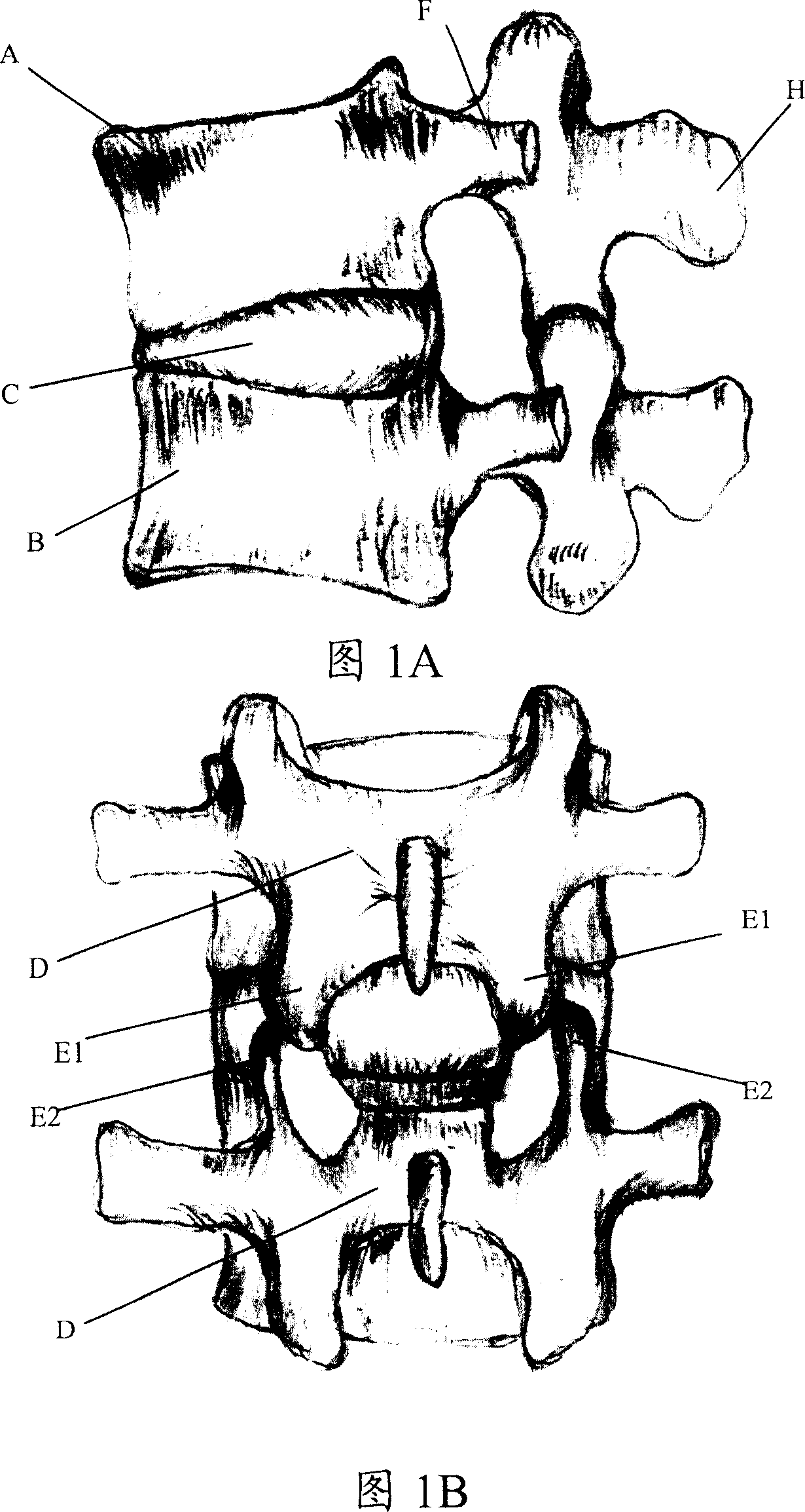
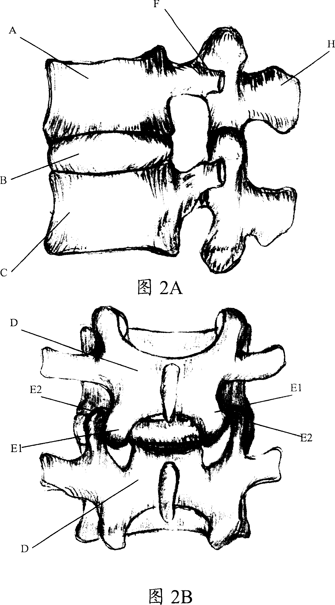
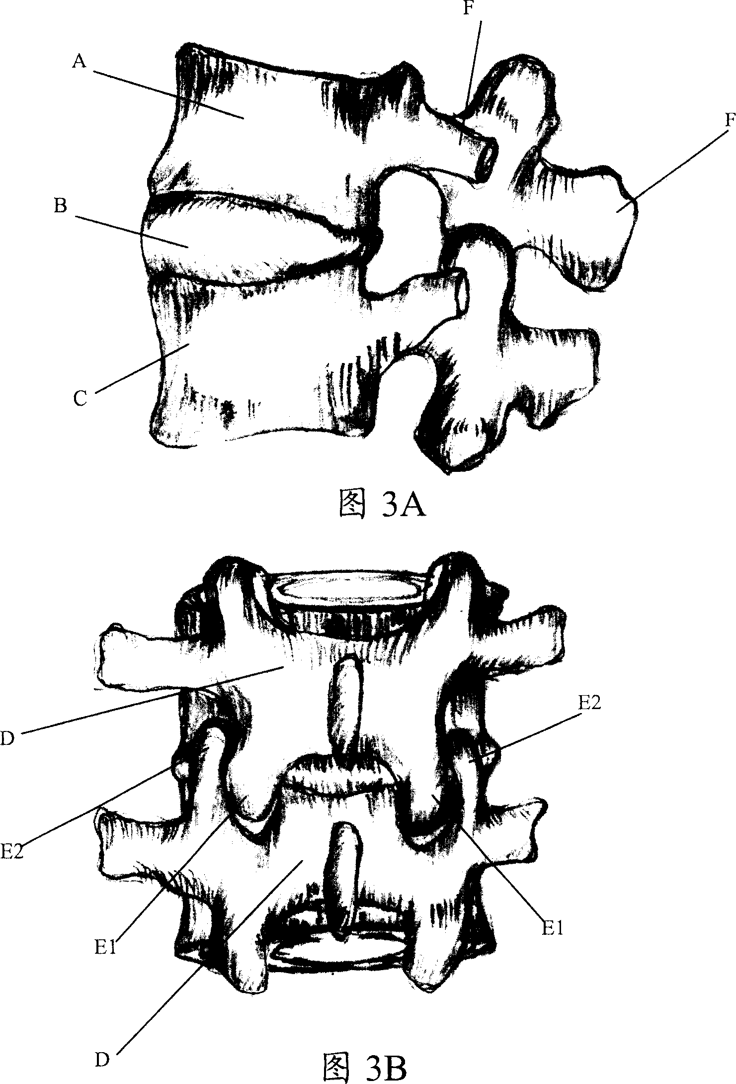
[0061] As shown in FIGS. 4A-10 , in this embodiment, a spring 33 is arranged between the ends 31 and 32 of the micro-motion facet joint 3 to form a spring-type micro-motion facet joint. In this way, after the spring-type fretting facet joint 3 is placed in the human body, it can replace the original bilateral facet joints of the human body to play an auxiliary supporting role for the upper and lower vertebral bodies 11, 12, and because it is an artificial joint, there is no human body principle. Bilateral facet joints can compress nerves due to bone hyperplasia caused by abnormal friction, which can greatly improve the success rate of intervertebral disc surgery and reduce the pain of patients.
[0062] Figures 4A and 4B are the side and rear views of the spring-type micro-motion facet joint 3 of this embodiment in the flexed position of the human body, and Figures 5A and 5B are the spring-type micro-motion facet joint 3 of this embodiment in the neutral position of the human b...
Embodiment 2
[0102] The basic structure of this embodiment is basically the same as that of Embodiment 1 except for the specific structure of the fretting facet joint, and will not be repeated here.
[0103] As shown in Figures 16-18, the difference between this embodiment and Embodiment 1 is that in this embodiment, the micro-motion facet joint 3 has an upper joint body 301 and a lower joint body 302, and the upper and lower joint bodies 301, One of the joint bodies of 302 is provided with a protrusion 303 protruding upwards or downwards, and a groove 304 corresponding to the protrusion 303 is provided on the other joint body, and the protrusion 303 is corresponding to the groove 304 Cooperate to form the concave-convex connection structure of the upper and lower joint bodies 301 and 302 .
[0104] As shown in Figure 19, as another optional implementation of this embodiment, the micro-motion facet joint 3 has an upper joint body 301 and a lower joint body 302, and one joint body of the up...
Embodiment 3
[0110] The basic structure of this embodiment is basically the same as that of Embodiment 1 except for the specific structure of the fretting facet joint, and will not be repeated here.
[0111] As shown in Figure 20, the difference between this embodiment and Embodiment 1 is that the micro-motion facet joint 3 described in this embodiment has an upper joint body 301 and a lower joint body 302, and the upper and lower joint bodies 301, 302 are both An arc-shaped protruding end portion 303 is provided. The fretting facet joint 3 also has a disc 304, on which two arc grooves (not shown) are arranged, corresponding to each arc protruding end respectively, and each arc protruding There is a pin 305 on the end, and this pin 305 is guided to slide in the arc groove on the disc (preferably, although not shown in the figure, but the following structure is easy to understand for the skilled person, the The arc-shaped slot can be a dovetail slot or trapezoidal slot structure with a sma...
PUM
 Abstract
Description
Claims
Application Information
 - R&D
- Intellectual Property
- Life Sciences
- Materials
- Tech Scout
- Unparalleled Data Quality
- Higher Quality Content
- 60% Fewer Hallucinations
Browse by: Latest US Patents, China's latest patents, Technical Efficacy Thesaurus, Application Domain, Technology Topic, Popular Technical Reports.
© 2025 PatSnap. All rights reserved.Legal|Privacy policy|Modern Slavery Act Transparency Statement|Sitemap|About US| Contact US: help@patsnap.com


