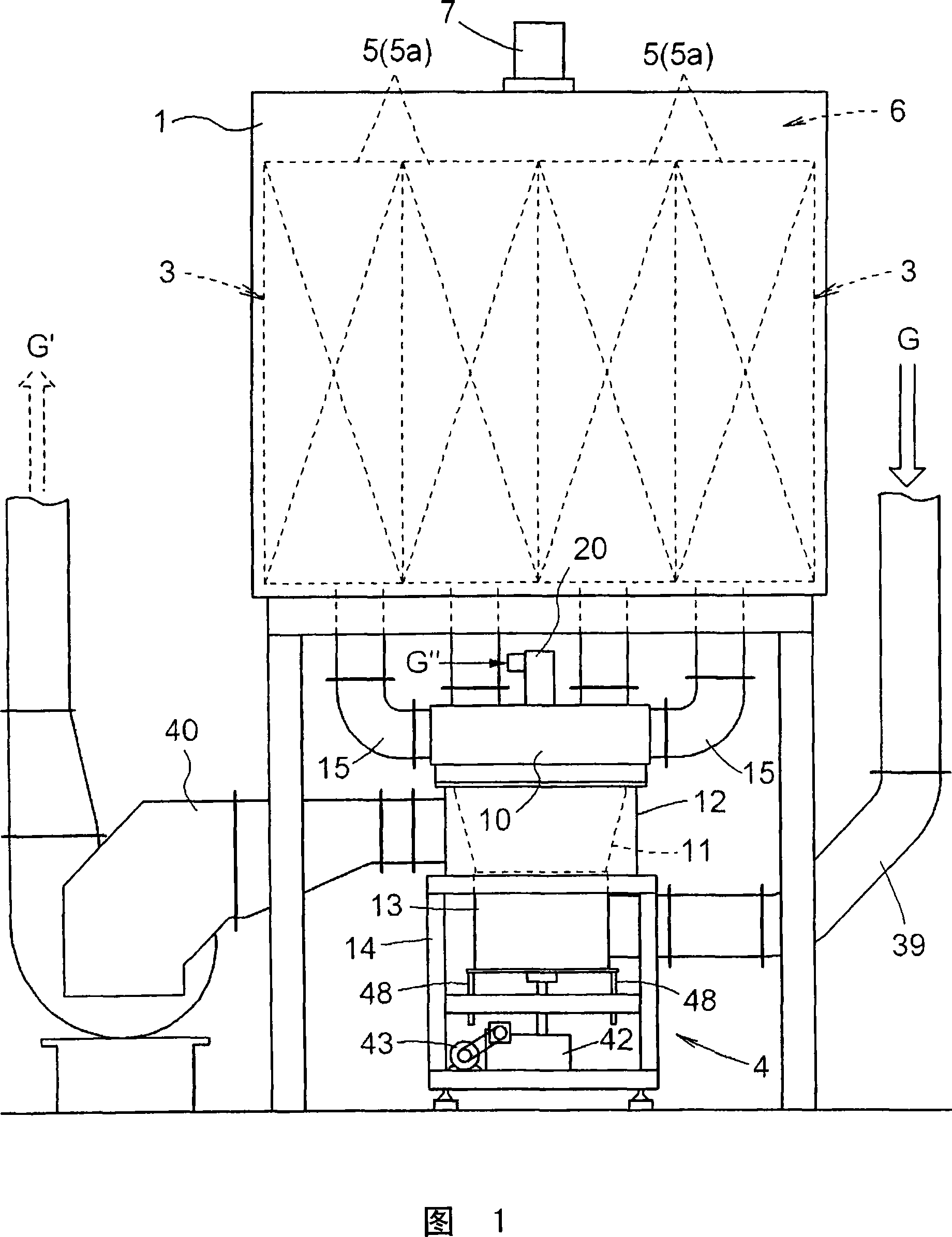
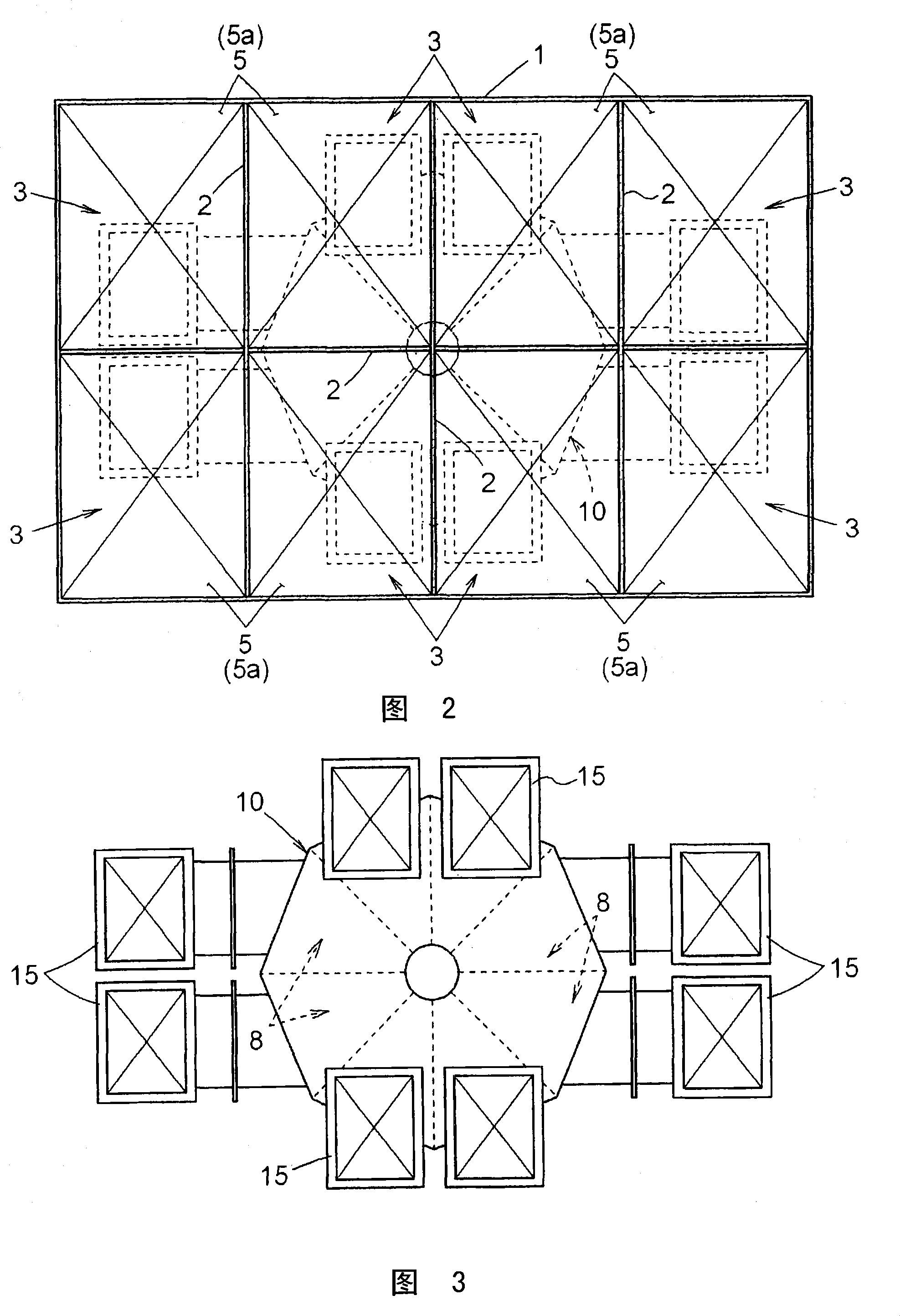
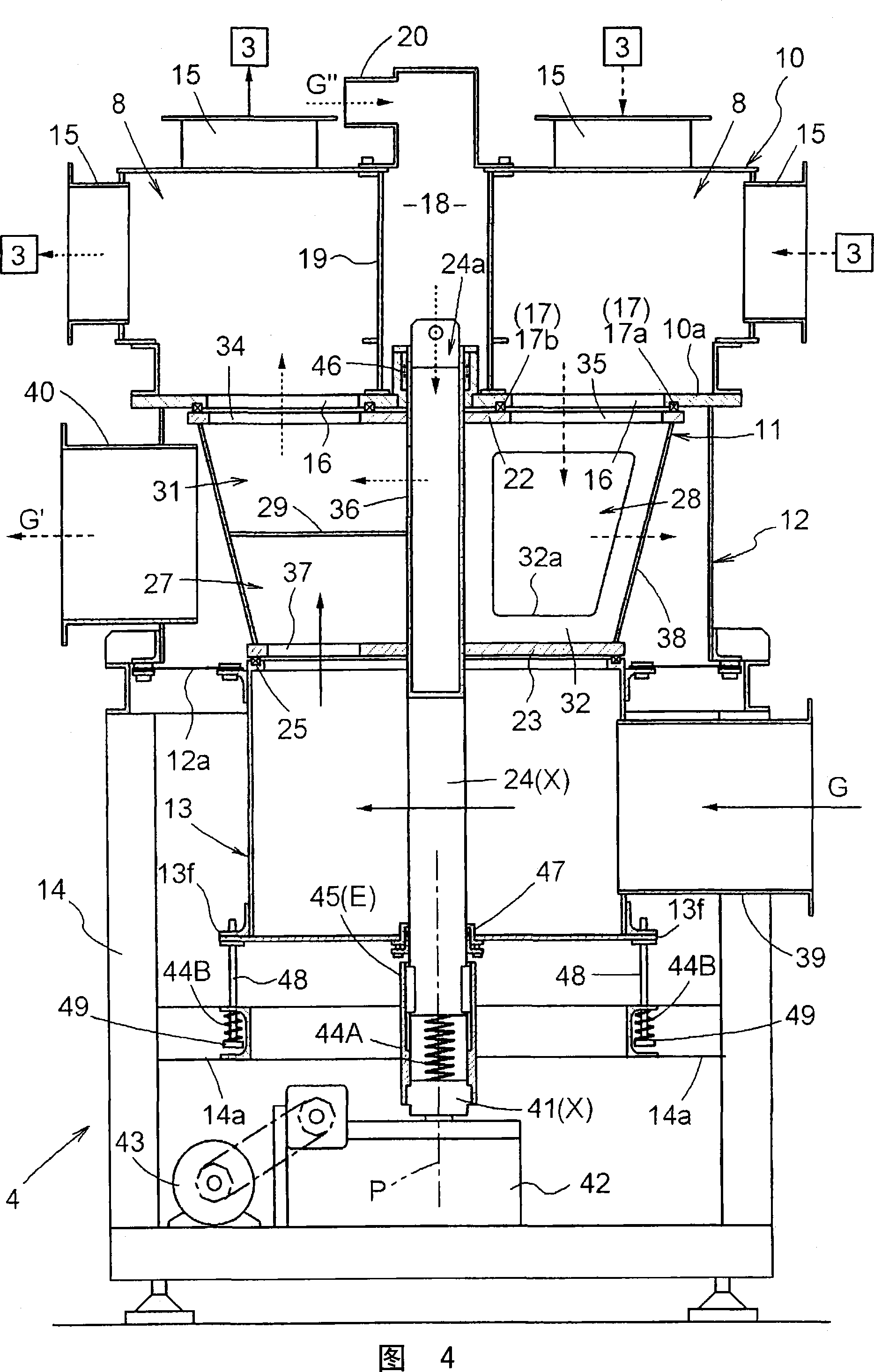
Heat accumulating gas processing system
A gas treatment and regenerative technology, applied in regenerative heat exchangers, valve devices, indirect heat exchangers, etc., can solve the problems of complex device structure, easy to loose, difficult to make devices, etc., and reduce the production accuracy. , The effect of improving sealing and simple structure
- Summary
- Abstract
- Description
- Claims
- Application Information
AI Technical Summary
Problems solved by technology
Method used
Image
Examples
no. 2 approach
[0269] Fig. 10 shows a thermal storage type gas processing device in which the thermal storage type gas processing device shown in the first embodiment is improved in practice of the present invention. In this regenerative gas treatment device, the combination of the distributor 10, the valve body device 12, and the gas chamber device 13 shown in the first embodiment is equipped upside down (that is, the gas chamber device is pressed from top to bottom). 13. The order of the valve body device 12 and the distributor 10 is equipped), so that the valve body 11 can freely displace in the up and down direction (far and near direction) relative to the fixed air chamber device 13, so that the distributor 10 can move up and down relative to the valve body 11. Free displacement in the direction (far and near direction).
[0270] Like the first embodiment, the valve body 11 built in the valve body 12 is configured to be rotated by a motor 43 via a drive rotation shaft 41 connected to a ...
no. 3 approach
[0279] Fig. 5, Fig. 11 and Fig. 12 show a thermal storage type gas processing device obtained by improving the thermal storage type gas processing device shown in the first embodiment and the second embodiment in practice of the present invention. In this thermal storage type gas treatment device, flange portions 24f and 41f are respectively formed on the connecting portion of the cylindrical rotating shaft 24 of the valve body 11 and the drive rotating shaft 41 . On the cylindrical rotating shaft side flange portion 24f, four threaded holes are provided at equal intervals around the axis P, and the threaded holes are used for screwing and inserting the connecting cylindrical rotating shaft 24 and the drive rotating shaft 41 (that is, The bolt 50 for connecting the rotating shaft X) formed by the cylindrical rotating shaft 24 and the driving rotating shaft 41, and the driving rotating shaft side flange portion 41f facing the above-mentioned four threaded holes 24b in the direct...
Embodiment approach
[0289] Next, other embodiments of the present invention will be listed.
[0290] In the first and third embodiments, in order to support the valve body 11 in a state of being freely displaceable in the far-near direction with respect to the distributor 10 and push the valve body toward the side of the distributor 10 by the biasing mechanism, the valve The urging mechanism for the body is arranged on the side of the air chamber 13, and acts on the valve body 11 to push it toward the side of the distributor 10 by means of the urging force applied by the urging mechanism for the valve body toward the elongated side. However, this method may not be adopted, and the valve body can be arranged on one side of the distributor 10 with a force applying mechanism, and the valve body 11 will act on the valve body 11 by means of the force applied by the valve body to the shortened side. It pulls towards the dispenser 10 side.
[0291] Similarly, in the second embodiment, in order to suppo...
PUM
 Abstract
Description
Claims
Application Information
 - R&D
- Intellectual Property
- Life Sciences
- Materials
- Tech Scout
- Unparalleled Data Quality
- Higher Quality Content
- 60% Fewer Hallucinations
Browse by: Latest US Patents, China's latest patents, Technical Efficacy Thesaurus, Application Domain, Technology Topic, Popular Technical Reports.
© 2025 PatSnap. All rights reserved.Legal|Privacy policy|Modern Slavery Act Transparency Statement|Sitemap|About US| Contact US: help@patsnap.com


