
Magnetic field method for sealing air gap

An air-gap magnetic field and air-gap technology, applied in the field of soft sealing, can solve the problems of large gap length, insufficient space, air leakage, etc.

Inactive Publication Date: 2007-07-25
SHIJIAZHUANG RAILWAY INST
View PDF1 Cites 7 Cited by
  • Summary
  • Abstract
  • Description
  • Claims
  • Application Information

AI Technical Summary

Problems solved by technology

However, this utility model has the following problems: (1) The length of the gap between the movable baffles arranged on the side baffles of the sintering machine trolley is relatively large, which is easy to form new air leakage; (2) The space on both sides of the old sintering machine is small , There is often not enough space when installing a movable baffle on the side baffle of the sintering machine trolley; (3) This device is only suitable for sealing the gap between the sintering machine trolley and the bellows, and it is suitable for the gap between the head and tail of the sintering machine and such as The sealing problem of the air gap such as the shaft head of the gas booster pump has not been solved

Method used


Image

  • Magnetic field method for sealing air gap

Examples


Embodiment 1

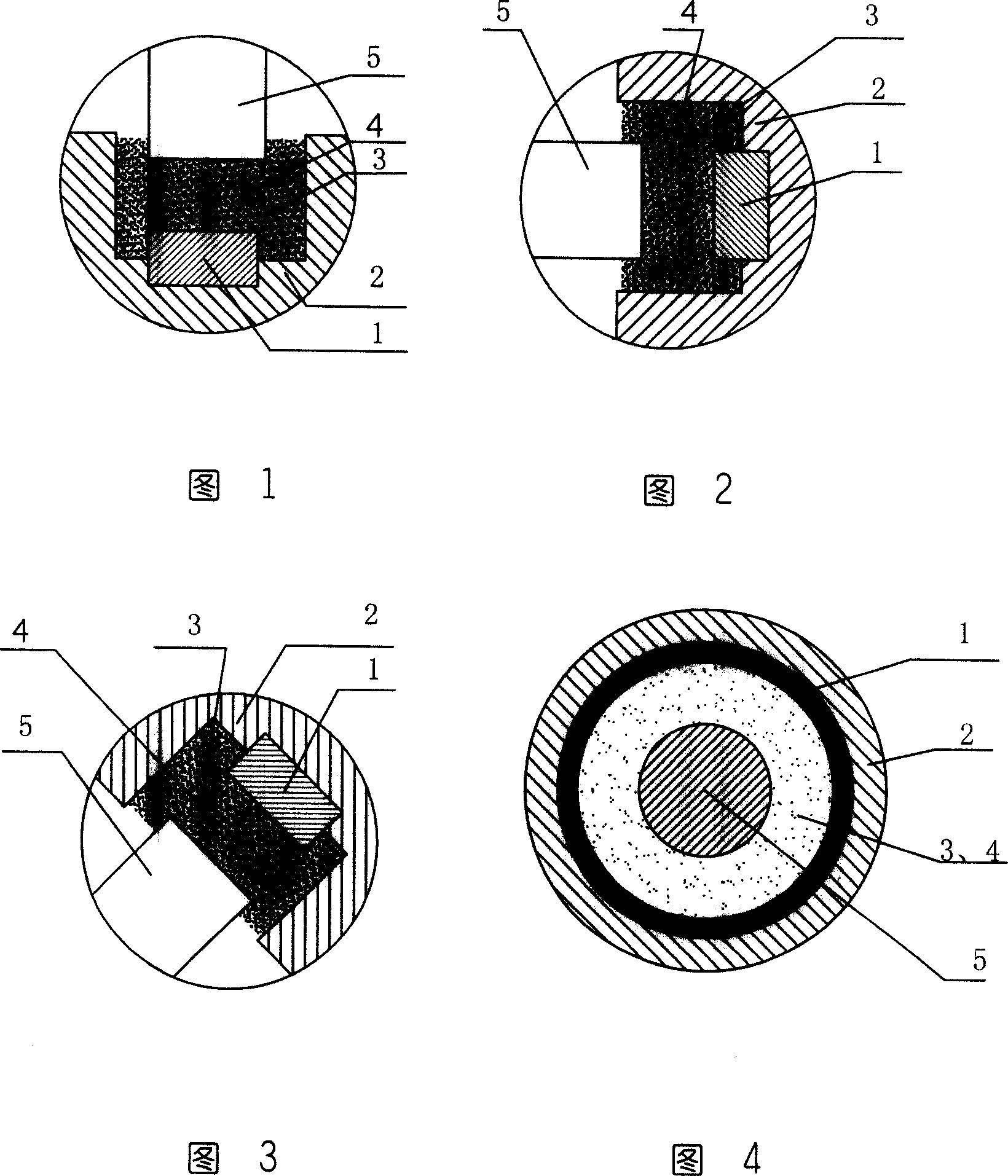
[0023] As shown in Fig. 1, the magnetic field sealing method of the present invention is adopted at the bottom of the trolley for the air gap between the sintering machine trolley and the bellows, and the magnetic field source 1 adopts the sintered NdFeB permanent magnet with the highest magnetic performance at present. A magnetic field is generated in the air gap of the sealing groove 4 formed between the fixed object 2—the bellows and the moving object 5—the sealing plate moving with the trolley, and the magnetic sealing medium 3 is filled in the magnetic field. The magnetic sealing medium is restrained by the magnetic field in the air gap of the sealing groove 4 and exists in the sealing groove to achieve the purpose of sealing.

[0024] The magnetic sealing medium used in this embodiment is composed of 80% ferrite or magnetically permeable materials NdFeB, iron, cobalt, nickel with a particle size of less than 5 μm plus 20% liquid dispersion material. The weight ratio of th...

Embodiment 2

[0027] As shown in Figure 4, the air gap at the shaft end of the gas pressurizer is sealed. The magnetic field source 1 adopts the sintered NdFeB permanent magnet with the highest magnetic performance at present, so that the fixed body 2-bearing seat and the mobile body 5-the impeller shaft form a A magnetic field is generated in the air gap of the ring groove 4; the magnetic sealing medium 3 is filled in the magnetic field. The magnetic sealing medium 3 is constrained by the magnetic field in the air gap 4 and exists in the air gap 4 to achieve the purpose of sealing.

[0028] The magnetic sealing medium 3 used in this embodiment is composed of 60% of the magnetically permeable material NdFeB powder with a particle size less than 5 μm plus 40% of the liquid dispersion material, and the weight ratio of the liquid dispersion material is polyethylene glycol 50 (polymerization degree 2000), three Ethanolamine 5, water balance. In addition to realizing the sealing function, it al...


PUM

PropertyMeasurementUnit
Granularityaaaaaaaaaa

Abstract

The present invention provides a magnetic field sealing method of air-gap. It is characterized by that on the air-gap of fixed body to be sealed a sealing groove correspondent to contact surface of mobile body is set, in the sealing groove bottom portion a magnetic field source is set, the groove interior is filled up with magnetic sealing medium to form magnetic field. The invented magnetic field flexible sealing theory is characterized by that in the air-gap to be sealed a magnetic field is created, the contact surface of said air-gap is filled up with magnetic sealing medium, under the action of magnetic field in the air-gap said magnetic sealing medium can be stably stored in the sealed air-gap, so that said sealed portion can obtain 'zero' leakage.

Description

technical field [0001] The invention relates to a magnetic field sealing method of an air gap, which is a soft sealing method. It is mainly used in the sealing field of industrial media such as the air gap between the head of the sintering machine, the trolley and the bellows in the metallurgical industry, the shaft end of the gas pressurizer and other moving air gaps and static air gaps, and belongs to the field of sealing technology. Background technique [0002] The economic loss caused by air leakage in sintering machines in the national metallurgical industry reaches more than 4 billion yuan per year. The air gap between the head of the sintering machine, the trolley and the bellows is the main reason for the air leakage of the sintering machine, low sintering production efficiency and high energy consumption. Another example is the frequent leakage of gas at the shaft end of the gas pressurizer, or the like. At present, the sealing of these parts adopts the mechanica...

Claims


Application Information

Patent Timeline
IPC IPC(8): F16J15/43F27B21/08
Inventor 于旭光樊云昌付华秦茶许昌玲
Owner SHIJIAZHUANG RAILWAY INST
Learn More