Liquid crystal 3D plane compatible display
A liquid crystal display and display technology, applied in three-dimensional systems, static indicators, instruments, etc., can solve the problems of difficult popularization, high cost, complex structure, etc., and achieve the effect of simple implementation and use, low cost, and mature technology.
- Summary
- Abstract
- Description
- Claims
- Application Information
AI Technical Summary
Problems solved by technology
Method used
Image
Examples
Embodiment 1
[0027] Method 1 is described in detail as follows:
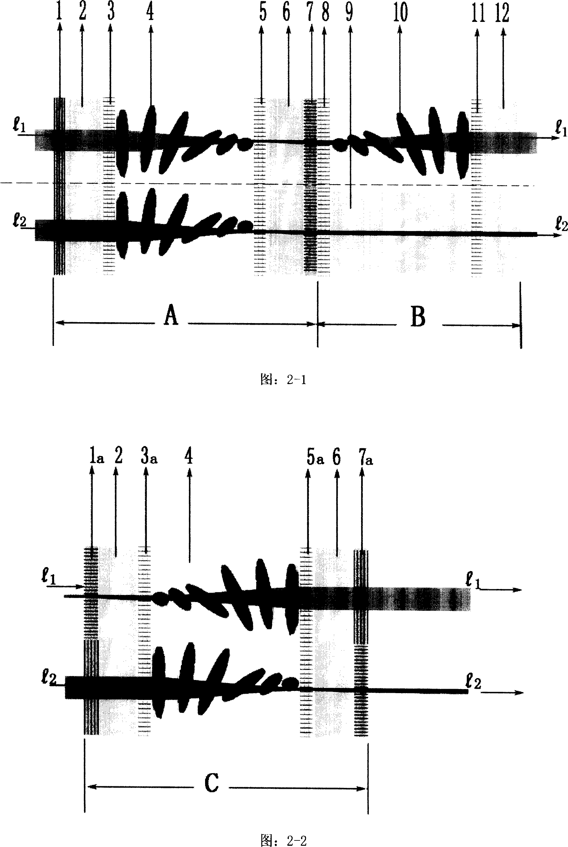
[0028] Figure 2-1 shows a cross-sectional view of the working principle of adding a liquid crystal light interlaced twisting layer, where part A is the original basic structure of the liquid crystal, and part B is the added part.
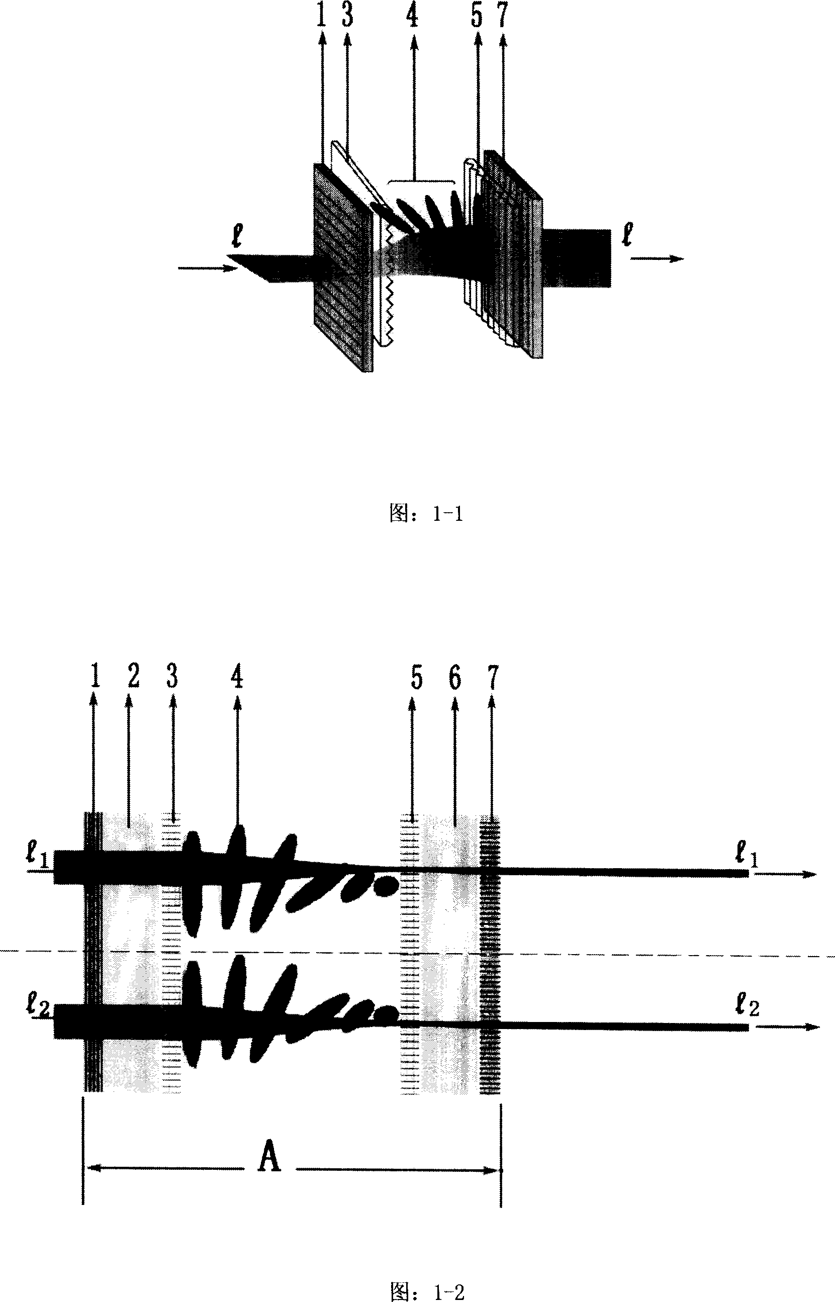
[0029] Among them, part A of Figure 2-1 is the working principle of conventional liquid crystals. The light passes through 1 incident light polarizing film -> 2 glass -> 3 guiding film -> 4 liquid crystal -> 5 guiding film -> 6 glass -> 7 outgoing polarized light For each layer of the film, the light is twisted by 4 liquid crystals, and when it is emitted, the amplitude of the light has been twisted by an angle of 90 degrees (also refer to Figure 1-1).
[0030] Part B is an added part of the present invention, and its working principle is: when the pipeline exits the seventh layer, a layer of liquid crystal light twisting layer is added alternately, and the upper part of Figure 2-1 is the line wit...
Embodiment 2
[0035] The second method is described in detail as follows:
[0036] As shown in Figure 2-2: when manufacturing a liquid crystal display, the corresponding interlaced vertical mutual polarization process is performed on the 1a incident polarizer and the 7a output polarizer, and the 3a and 5a guiding films of the liquid crystal are also correspondingly processed. Interlaced lines are processed perpendicular to each other. After that, the whole LCD screen works normally like this, the light l1 and l2 pass through 1a polarizer -> 2 glass -> 3a liquid crystal guide plate -> 4 liquid crystal twisted 90 degrees -> 5a guide plate -> 6 glass -> due to The polarized light of 1a and 7a is perpendicular to each other, and the light is twisted by 90 degrees just to be sent out. Because the two polarizing films inside and outside the corresponding position (same pixel) are rotated 90 degrees at the same time, and the liquid crystal is also rotated 90 degrees, so all the circuit work does ...
Embodiment 3
[0038] The details of method three are as follows:
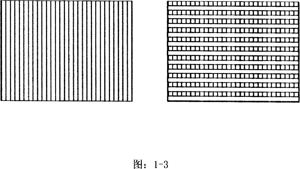
[0039]The difference between this scheme and ordinary liquid crystal display is that the incoming and outgoing light polarizers are not in the same direction of the whole sheet, but interlaced and vertical (as shown in Figure 1-3b). It is a mixed product of the two working modes of constant light and long dark (here it is assumed that the odd field is long dark, as shown in the figure: 2-3a and the half of the dotted line in Figure 2-3b; the even field is the long bright mode, as shown in the figure : 2-3a and the lower half of the dotted line in Fig. 2-3b). The light guides of the two polarizing films of a normally bright liquid crystal display are perpendicular to each other, as shown in Figure 1-1 and 1 and 7 in Figure 1-2, that is, as shown in Figure 2-3a and under the dotted line in Figure 2-3b Half of the area belongs to the current working mode of liquid crystal. In this case, light can pass through without power on,...
PUM
 Abstract
Description
Claims
Application Information
 - R&D
- Intellectual Property
- Life Sciences
- Materials
- Tech Scout
- Unparalleled Data Quality
- Higher Quality Content
- 60% Fewer Hallucinations
Browse by: Latest US Patents, China's latest patents, Technical Efficacy Thesaurus, Application Domain, Technology Topic, Popular Technical Reports.
© 2025 PatSnap. All rights reserved.Legal|Privacy policy|Modern Slavery Act Transparency Statement|Sitemap|About US| Contact US: help@patsnap.com


