
Ventilator turbine of wind power generator set

A technology of wind power generating set and flat machine, which is applied in the direction of wind power generator components, wind power motor combination, wind power engine, etc. It can solve the problems of easily damaged wind blades, low output power, expensive materials, etc., and achieves good wind resistance and high output power. The effect of high power and multiple economic benefits

Inactive Publication Date: 2007-07-18
邱惠民
View PDF1 Cites 0 Cited by
  • Summary
  • Abstract
  • Description
  • Claims
  • Application Information

AI Technical Summary

Problems solved by technology

The current wind generators basically use paddle-type wind blades. When using wind power generation, due to the small thrust coefficient, the wind blades need a large wind speed at the start-up stage, but the wind resistance is poor, and the wind speed reaches a certain level. It is easy to damage the wind blades, the available wind speed line segment is small, and the output power is small; and in order to meet the electricity demand, the existing generators are basically large, so for wind power generators, its blade volume It is also very large, difficult to manufacture, and the materials are relatively expensive
[0003] The utility model specification of patent No. ZL01266082.5 discloses a fan blade of a wind power generator, which is a telescopic adjustment rod corresponding to the fan blade pivotally arranged on the outer section of the operation axis of the fan blade on the wind power generator set. The other end of the telescopic adjustment rod is pivotally connected to the middle section of each fan blade; the advantage is that the tilt direction angle of the fan blades is adjusted by the telescopic adjustment rod to adapt to the change of wind direction. When running in the wind, the generator set also changes direction with a small angle to avoid fan The blades are damaged due to oblique wind force; and the outer end of the fan blades is designed as a pointed structure that is easy to attract lightning waves in the air, which can achieve the lightning protection effect of introducing lightning in the air to the ground; but it also does not solve the problem of low output power and available The problem of small wind speed line segment

Method used


Image

  • Ventilator turbine of wind power generator set
  • Ventilator turbine of wind power generator set
  • Ventilator turbine of wind power generator set

Examples


Embodiment Construction

[0026] The present invention will be further described in detail below in conjunction with the accompanying drawings and embodiments.

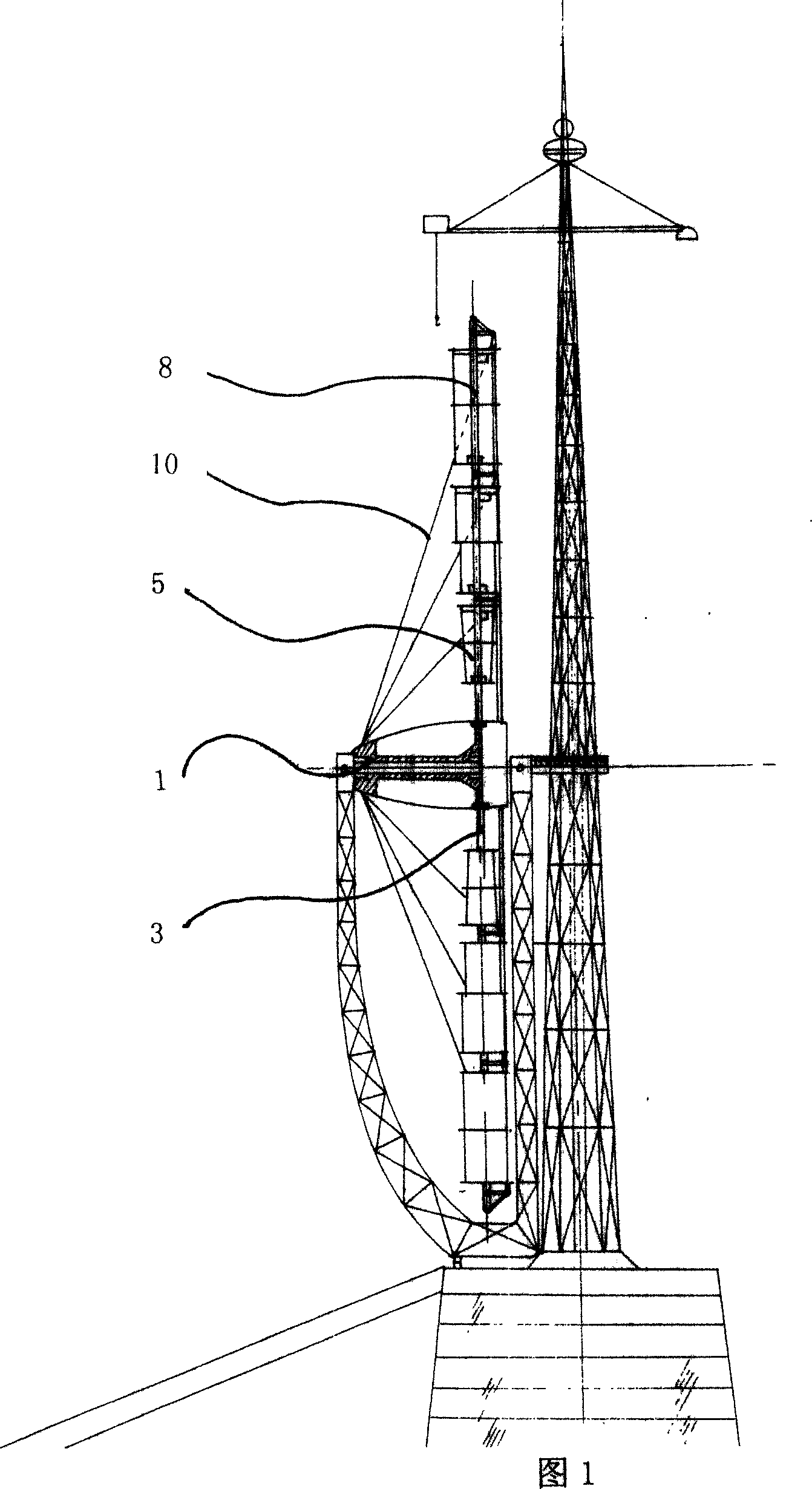
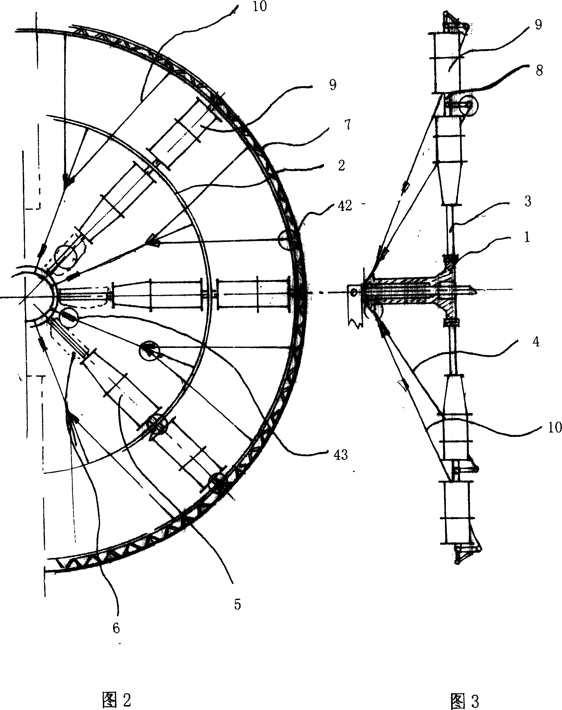
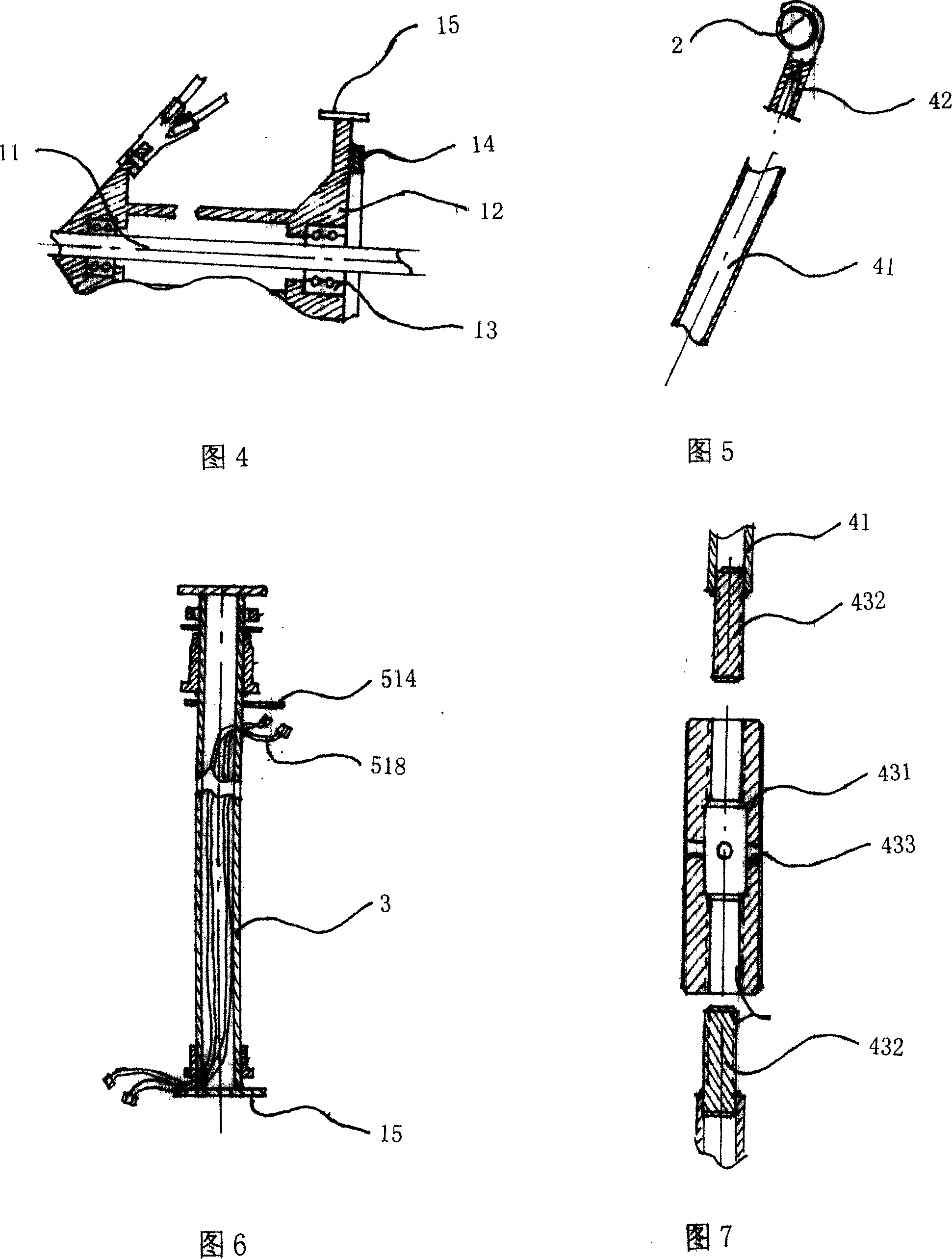
[0027] As shown in the figure, a wind turbine of a wind power generating set includes a central shaft assembly 1 and a fixed ring 2. The central shaft assembly 1 includes a fixedly arranged load-bearing shaft 11 and a main shaft sleeve coaxially sleeved on the load-bearing shaft 11. 12. The coaxial sleeve between the main shaft sleeve 12 and the load-bearing shaft 11 is provided with a main bearing 13. The end surface of the tail of the main shaft sleeve 12 is fixed with a transmission ring gear 14 connected to the generator. The main shaft sleeve 12 and the fixed ring 2 are respectively There are eight steel pipe shafts 3 and stress devices 4 evenly distributed along the circumferential direction. The stress device 4 is arranged between two steel pipe shafts 3. One end of the steel pipe shaft 3 is fixedly connected to the tail of the main shaf...


PUM


Abstract

The wind turbine for wind generator includes one central shaft, one fixing ring, two steel pipe axles to connect the ring to the central shaft, wind impellers capable of rotating around the shaft on the steel pipe axles, and driving mechanism on the wind impellers. The wind turbine has the advantages of great thrust coefficient, great output power and relatively low cost.

Description

technical field [0001] The invention relates to a wind power generator, in particular to a wind turbine of a wind power generating set. Background technique [0002] With the development of society, electricity occupies an increasingly important position in our daily life, and various power generation methods have emerged as the times require, mainly including wind power, hydropower and thermal power. The current wind generators basically use paddle-type wind blades. When using wind power generation, due to the small thrust coefficient, the wind blades need a large wind speed during the start-up stage, but the wind resistance is poor, and the wind speed reaches a certain level. It is easy to damage the wind blades, the available wind speed line segment is small, and the output power is small; and in order to meet the demand for electricity, the existing generators are basically large, so for wind power generators, its blade volume It is also very large, difficult to manufac...

Claims


Application Information

Patent Timeline
IPC IPC(8): F03D1/06F03D11/00F03D9/00F03D15/00F03D80/00
CPCY02E10/725Y02E10/722Y02E10/721Y02E10/72
Inventor 邱惠民
Owner 邱惠民
Learn More