Transit mixer for free-flowing media

A technology of flowing medium and mixing machine, which is applied in the direction of concrete transportation, cement mixing device, clay preparation device, etc., can solve the problems of complicated installation of supporting roller units, and achieve the effect of saving materials and increasing precision.

Active Publication Date: 2010-02-17
STETTER
View PDF8 Cites 0 Cited by
  • Summary
  • Abstract
  • Description
  • Claims
  • Application Information

AI Technical Summary

Problems solved by technology

However, mounting the support roller unit is very complicated, since on the one hand a precise alignment of the support roller unit on the base and a corresponding precise alignment of the rollers mounted in the support roller unit has to be ensured, thus requiring a great deal of adjustment work

Method used


Image

  • Transit mixer for free-flowing media
  • Transit mixer for free-flowing media
  • Transit mixer for free-flowing media

Examples


Embodiment Construction

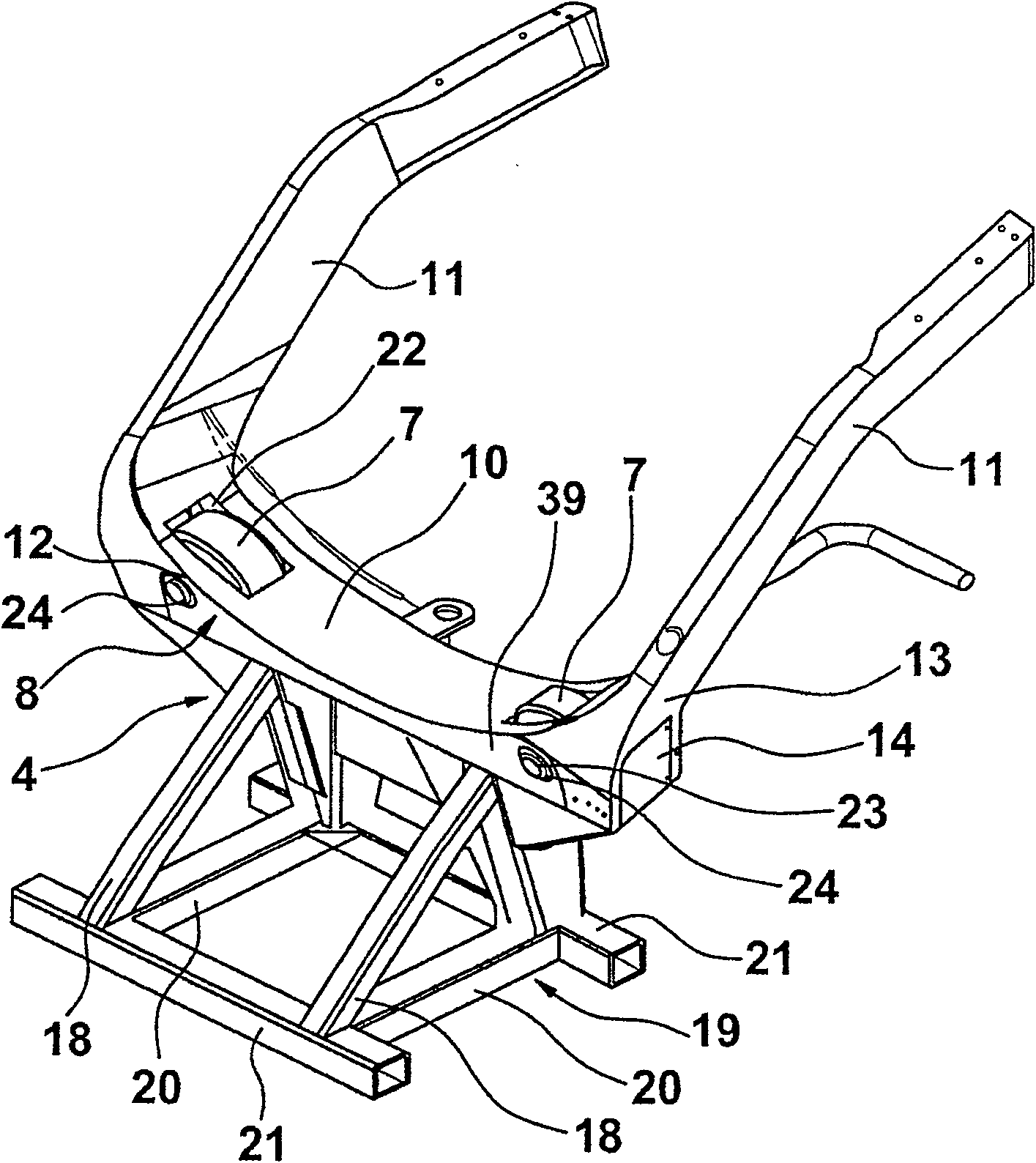
[0035] figure 1 A concrete mixer truck 1 in the form of a truck is shown having a frame 2 generally consisting of two parallel beams supporting front and rear bases 3 and 4 on which are housed and mounted a Similar viscous substances marked 5 agitator drum. A drive for the stirring drum 5 is installed in the area of ​​the front base 3 , but this is only shown schematically here. The mixing drum 5 is rotatably mounted on the base via a running support surface 6 formed on the rear of the drum. For this purpose, if figure 2 As shown, the base 4 has two rollers 7 which are rotatably mounted in the base 4 .

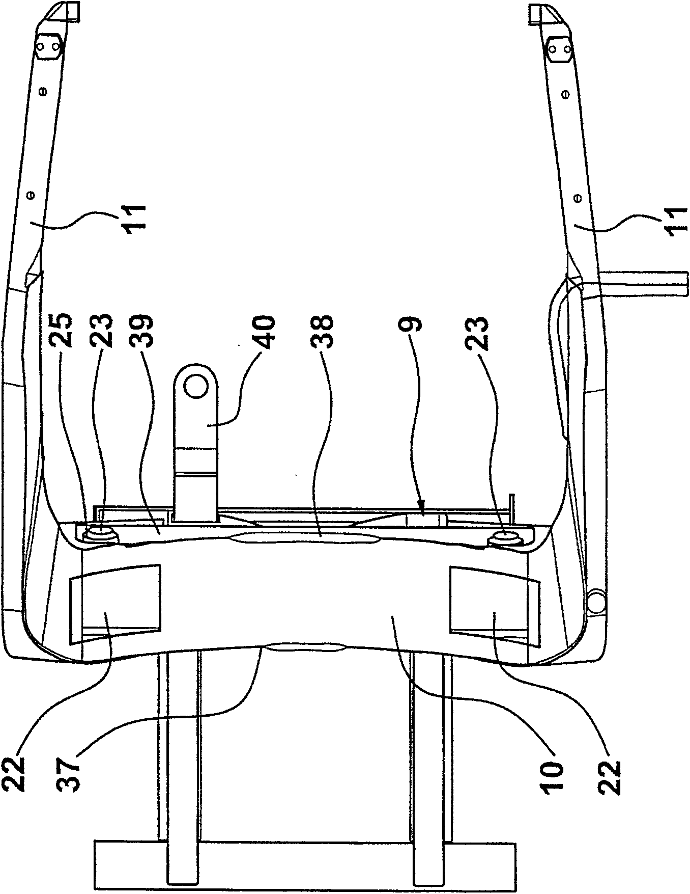
[0036] exist figure 2 and image 3 In the embodiment, the upper part of the base 4 is constituted by a box-shaped housing, which basically consists of a front base wall 8 and a image 3 The front base wall 8 and the rear base wall 9 are connected by a top wall 10 . The top wall has an arch adjusted to the diameter of the running support surface 6 of the mixing drum 5 ...


PUM


Abstract

The invention relates to a transit mixer for free-flowing media, in particular concrete, the mixing drum of said mixer being mounted on supports. According to the invention, the rollers that bear thecircular path of the mixing drum are partially sunk in the support housing.

Description

technical field [0001] The present invention relates to a transit mixer. Background technique [0002] This type of transport mixer (DE 44 31 501) has a front and rear base for supporting a mixing drum (mixing drum) on the vehicle frame, and its front base supports a mixing drum The drive and the rear base are provided with two rotatably mounted rollers on which the mixing drum supports itself with its peripheral running tread. The mounting of the rollers takes place via a corresponding roller support which has two opposite bearing plates in which the rollers are mounted. The roller supports are bolted to the upper side of the base by flange-side fillets. The disadvantage of this design is that the support roller bearings are easily contaminated and there is a relatively large gap between the running support surface and the upper side of the base, which results in an increased risk of accidents, because the Personnel can easily reach a given danger zone with their hands t...

Claims


Application Information

Patent Timeline
Patent Type & Authority Patents(China)
IPC IPC(8): B28C5/42B60P3/16
CPCB28C5/4265
Inventor 西格弗里德·布赫塔约亨·格利希佐兰·阿尼克
Owner STETTER
Why Eureka
Try Eureka