
Step-by-step type energy absorption device during collision of automobiles

An energy absorbing device and collision energy absorbing technology, applied in vehicle parts, transportation and packaging, substructure and other directions, can solve the problem of unfavorable energy absorbing occupant protection, can not achieve the effect of collision energy absorbing occupant protection, and the rear part of the collision acceleration peak is large. Body structure and other issues, to achieve the effect of simple and compact structure, wide application range and low cost

Inactive Publication Date: 2010-01-13
HUNAN UNIV
View PDF4 Cites 0 Cited by
  • Summary
  • Abstract
  • Description
  • Claims
  • Application Information

AI Technical Summary

Problems solved by technology

Depend on Figure 4 It can be seen that the body structure corresponding to the acceleration curve cannot achieve a good impact energy absorption and occupant protection effect.
Especially when the body shape requires a small collision energy absorption length, increasing the energy absorption effect only by increasing the wall thickness of the square energy-absorbing beam will lead to a larger collision acceleration peak and early buckling of the rear body structure, which is not conducive to energy absorption during the collision process and occupant protection

Method used


Image

  • Step-by-step type energy absorption device during collision of automobiles
  • Step-by-step type energy absorption device during collision of automobiles
  • Step-by-step type energy absorption device during collision of automobiles

Examples


Embodiment Construction

[0014] The present invention will be described in further detail below in conjunction with the accompanying drawings and specific embodiments.

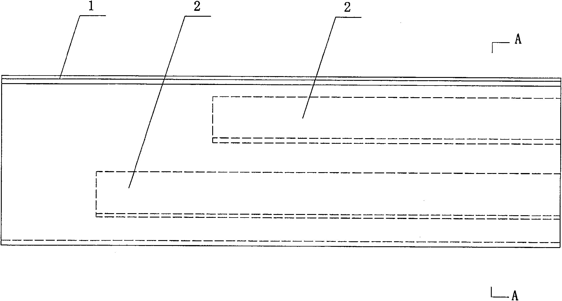
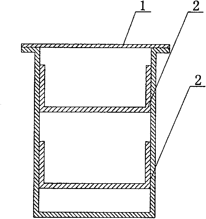
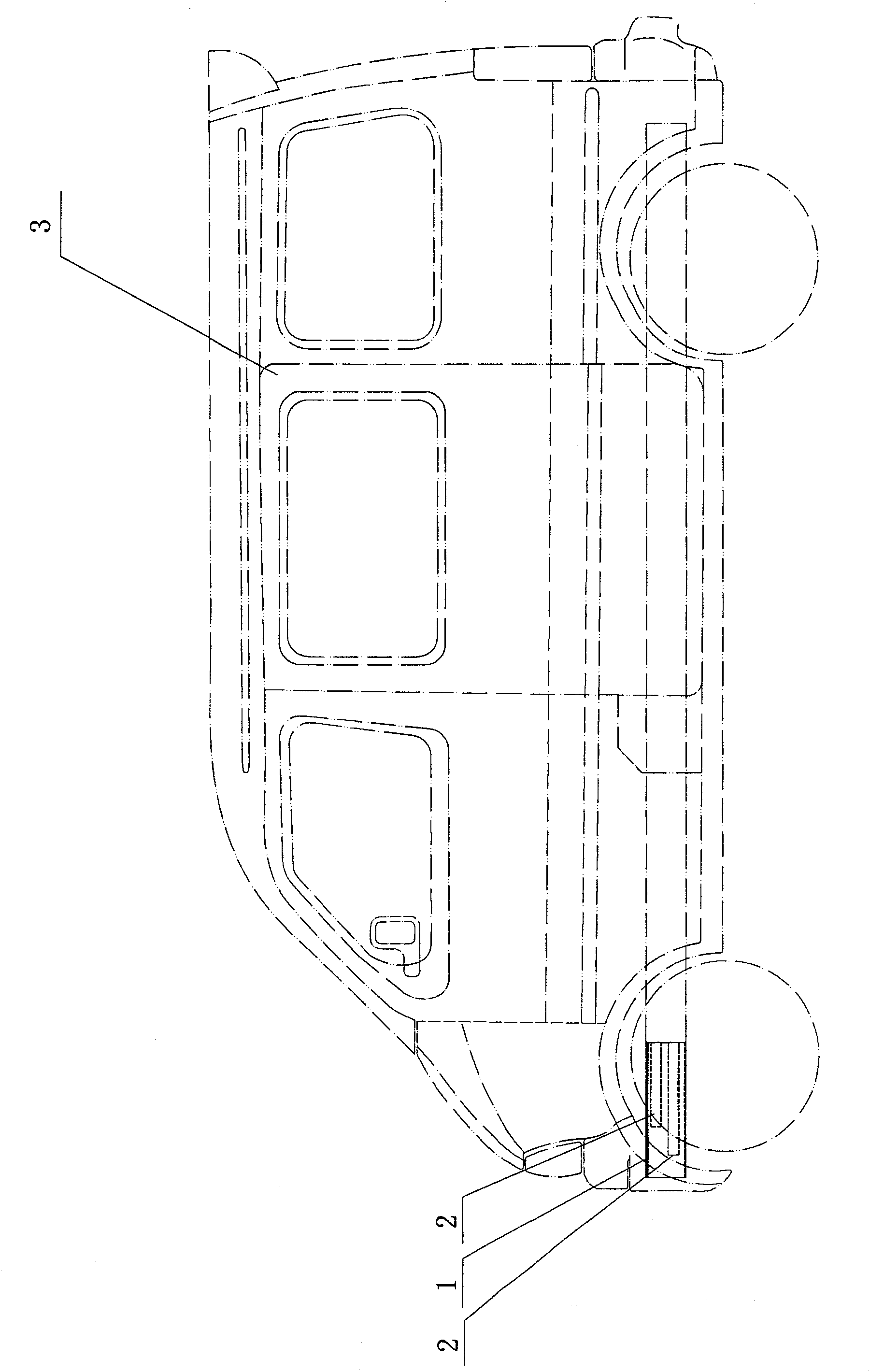
[0015] Such as figure 1 , figure 2 and image 3 As shown, the automobile collision energy-absorbing device step by step of the present invention includes an energy-absorbing beam 1, and one or more reinforcing plates 2 are installed inside the energy-absorbing beam 1. In this embodiment, the energy-absorbing beam 1 is a square beam with a hollow inside. The energy-absorbing beam 1 is provided with two reinforcing plates 2 , both of which are in the shape of channel steel, and the arrangement direction of the reinforcing plates 2 is the same as that of the energy-absorbing beam 1 . The reinforcing plate 2 is welded and fixed in the energy-absorbing beam 1. The length and thickness of the two reinforcing plates 2 can be selected and combined according to actual needs. When it is necessary to increase or reduce the energy-absorbing ...


PUM


Abstract

A multi-stage collision energy sucking mechanism for car is composed of an energy sucking beam, and one or more reinforcing plates in said sucking beam for sucking the collision energy one by one.

Description

technical field [0001] The invention mainly relates to the structural design field of automobile collision safety, in particular to a step-by-step energy-absorbing device for automobile collision. Background technique [0002] In the prior art, in order to ensure the safety of the drivers and passengers when the car collides, generally an energy absorbing device is provided at the front of the car. The conventional energy absorbing device is mainly a square longitudinal beam. However, the collision acceleration curve of this square energy-absorbing beam structure usually produces a peak at the beginning of the collision process, and then, due to the structural yield, the collision acceleration curve will produce a trough again, and then it will be at a lower level, which is different from the There is a large gap in the ideal uniform collision energy absorption process, and it is difficult to achieve a good energy absorption effect within the shortest possible energy absorpt...

Claims


Application Information

Patent Timeline
Patent Type & Authority Patents(China)
IPC IPC(8): B62D21/15
Inventor 曹立波白中浩
Owner HUNAN UNIV
Learn More