Rotor for electric generator

A generator and rotor technology, applied in electrical components, electromechanical devices, electric components, etc., can solve problems such as large space and thick insulation

Active Publication Date: 2010-01-06
GENERAL ELECTRIC TECH GMBH
View PDF3 Cites 0 Cited by
  • Summary
  • Abstract
  • Description
  • Claims
  • Application Information

AI Technical Summary

Problems solved by technology

The disadvantage of this transition is that the insulation is very thick, i.e. a large space is required for electromagnetically inert materials

Method used


Image

  • Rotor for electric generator
  • Rotor for electric generator
  • Rotor for electric generator

Examples


Embodiment Construction

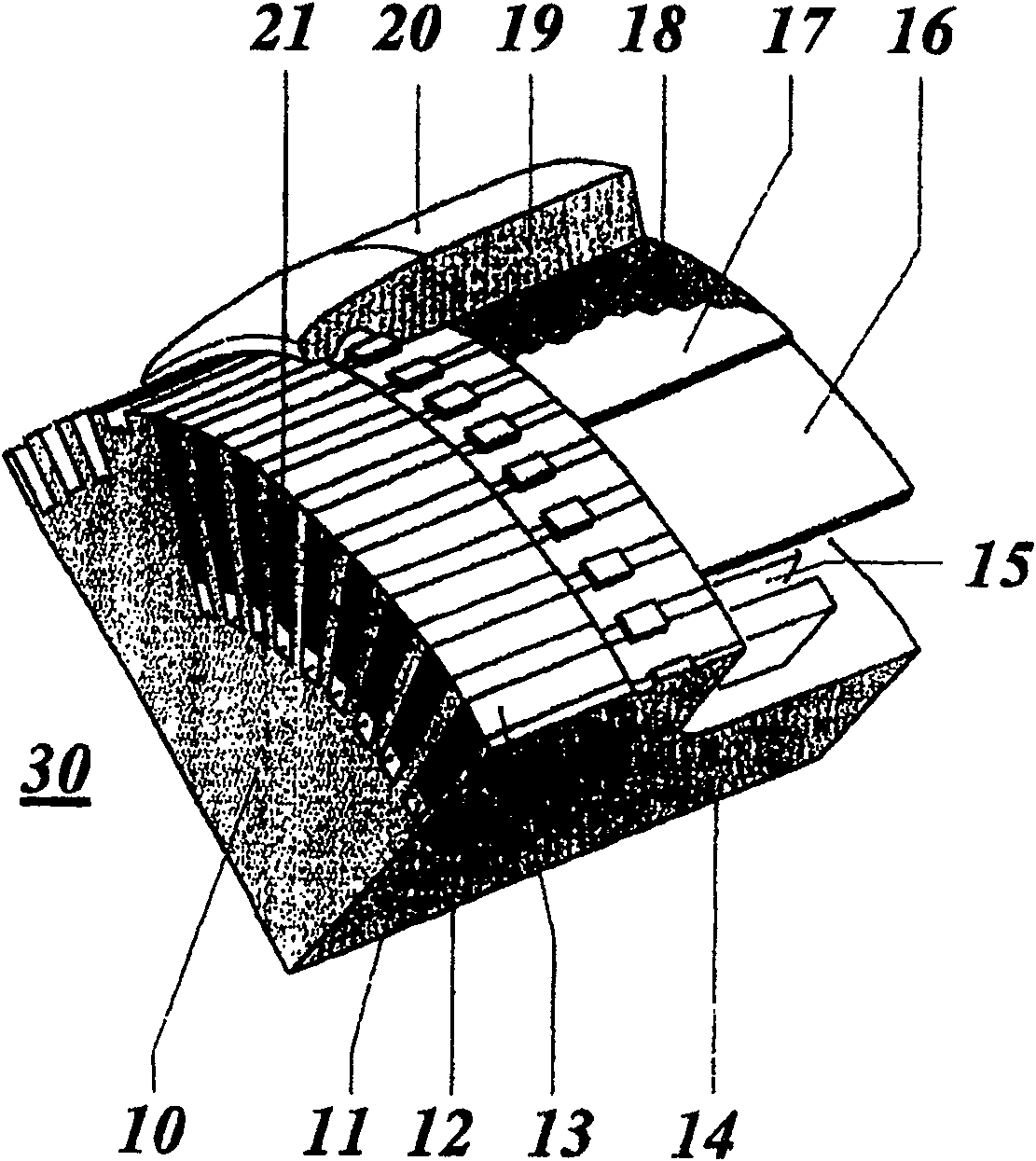
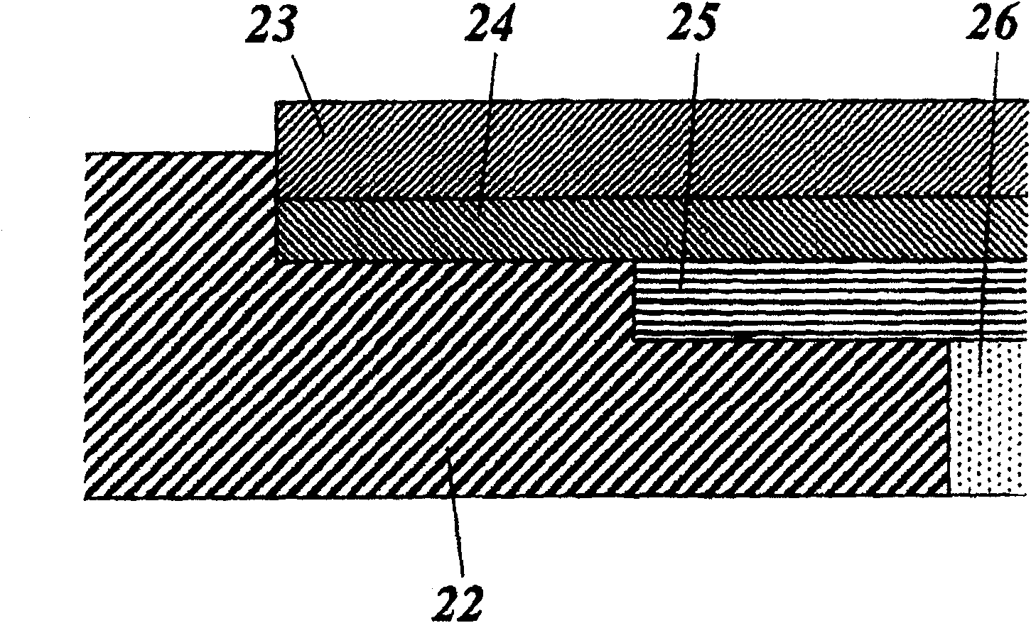
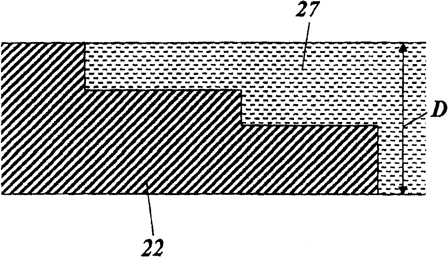
[0025] exist image 3 in a similar figure 2 The illustration shows the transition from an axially stepped cover channel 22 to a radially rigid cover insulating element 27 of almost the same thickness D according to a preferred embodiment of the invention. Figure 4 with a similar figure 1 A view of the rotor 30' according to a preferred embodiment of the invention is shown. The cover insulation section 27 connected in a stepped manner on the cover channel 22 is located here directly below the cover ring 19 of the rotor cover 20 , that is to say without an intervening protective cover plate. Instead of the cover insulating section 27 it is also possible to use a one-piece slotted cover insulating ring.

[0026] The cover insulating element 27 is formed, for example, as a half shell. They have the following features and advantages:

[0027] ●The insulation section of the cover has high radial rigidity.

[0028] ●The insulation section of the cover has high tangential rigi...


PUM


Abstract

The invention relates to a rotor for a generator, more particularly a rotor for a high-power turbogenerator. The rotor has slots extending axially in a rotor body and inserted with conductor bars, wherein the conductor bars are axially supported in the slots via wedges and eclectically connected with each other at the end parts of rotor windings on the end of the rotor body; and the end parts of the rotor windings are respectively covered by rotor caps that are pushed above the end of the rotor body. The rotor further comprises electrically insulating covering channels respectively arranged between a respective uppermost conductor bar and a respective wedge in a respective slot, and cap insulating members respectively arranged between the respective rotor winding and the respective rotor cap. The invention simplifies the structure of the rotor body while keeps the mechanical and electrical characteristics good or better. The covering channels have axially stepped ends on the end of the rotor body. The cap insulating member comprises rings or cap insulation sections formed towards the rotor body so as to fit with the axially stepped ends of the covering channels. The rotor caps are directly pushed on the cap insulating members.

Description

technical field [0001] The invention relates to the field of generators. The invention relates to a rotor for an electric motor, in particular for a high-power turbine generator. Background technique [0002] Such a rotor is known, for example, from document DE-A1-10119989 by the applicant. [0003] As the main element, the turbine generator consists of a figure 1 14) A rotatably supported rotor, which is concentrically surrounded by a stator. Examples of such turbogenerators and their rotors are known, for example, from the article K. Weigelt, "Konstruktionsmerkmalegrosser Turbogeneratoren", ABB Technik 1 / 1989, S.3-14. The rotor of this turbogenerator has a rotor ball with an enlarged diameter in the central area. exist figure 1 One end of one such rotor ball is shown in . Axial slots 11 for receiving conductor bars 12 of the rotor winding are provided on the outside of the rotor ball 10 of the rotor 30 . The conductor bars 12 are secured in the slots 11 by means of ...

Claims


Application Information

Patent Timeline
Patent Type & Authority Patents(China)
IPC IPC(8): H02K3/46H02K3/51
CPCH02K3/51
Inventor A·J·霍尔姆斯G·S·克莱因J·林德K·梅厄R·罗青格
Owner GENERAL ELECTRIC TECH GMBH
Why Eureka
Try Eureka