
Non-kinetic inherently safe tube-pool type reactor

An inherently safe, reactor technology, applied in the field of nuclear reactors, can solve problems such as core water loss acceleration, core water loss, and inability to escape, and achieve the effect of a reliable passive safety system

Active Publication Date: 2010-01-06
NUCLEAR POWER INSTITUTE OF CHINA
View PDF6 Cites 1 Cited by
  • Summary
  • Abstract
  • Description
  • Claims
  • Application Information

AI Technical Summary

Problems solved by technology

For the research-type tube pool reactors that have been built, from the perspective of existing safety standards, there are deficiencies
For example, the direction of water flow in the core of JMTR in Japan, ATR in the United States, and HFETR in China and CARR research reactors in China is from top to bottom, and there is a flow reversal process after the core is cut off; there is no second shutdown system; the waste heat export system is Active, reliable Power supply failure or failure of the waste heat export pump to start will cause serious consequences; in the event of main pipeline rupture and water loss (before the main pump outlet check valve), when the connecting valve between the voltage stabilizer and the stack container fails to close, the pressure stabilization The gas in the reactor will be pressed into the stack, causing the core to lose water faster, especially after the main pump outlet check valve is automatically closed after the flow is cut off, the gas cannot escape from the stack inlet pipe, and the core water flows downward under pressure, which may cause Core loss of water
Internationally, the research reactors whose fuel assemblies are subjected to high pressure and the fuel and material test tool reactors have not been able to solve the above problems well.

Method used


Image

  • Non-kinetic inherently safe tube-pool type reactor
  • Non-kinetic inherently safe tube-pool type reactor

Examples


Embodiment Construction

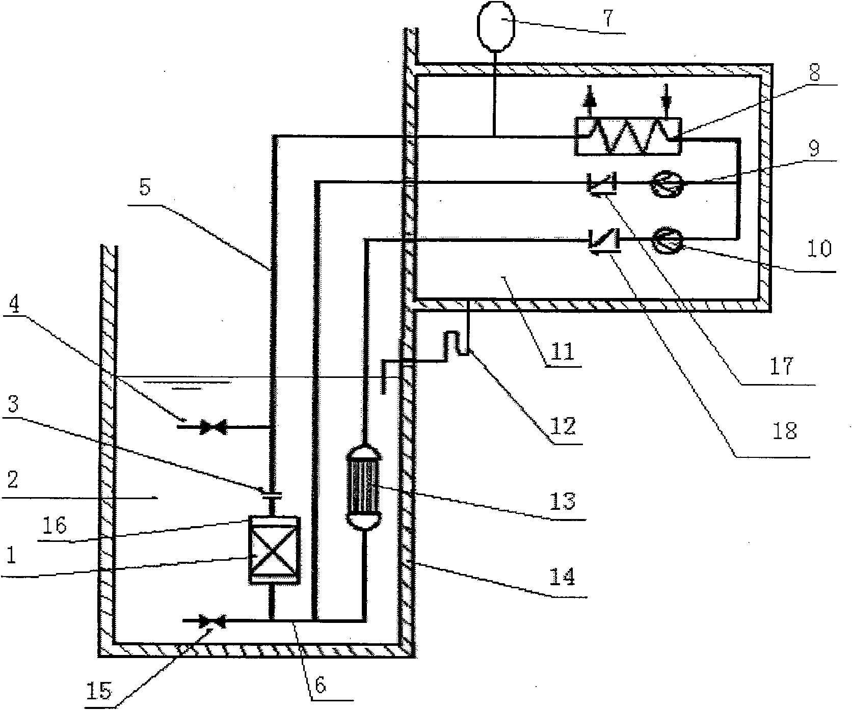
[0022] Such as figure 1 In the tube pool reactor shown, the reactor pressure vessel 16 is installed in the reactor pool 2, the reactor core 1 is installed in the reactor pressure vessel 16, and the upper part of the reactor pressure vessel 16 communicates with the main heat exchanger 8 through the reactor cooling water outlet pipe 5; The main heat exchanger 8 communicates with the reactor cooling water inlet pipe 6 through two parallel pipelines, one of which is connected with the reactor cooling water main pump 9 and the main pump outlet check valve 17 in sequence, and the other pipeline is connected with the waste heat The export pump 10, the waste heat export pump outlet check valve 18, the waste heat exchanger 13, and the waste heat exchanger 13 is located in the pool 2; the reactor cooling water inlet pipe 6 communicates with the lower part of the reactor pressure vessel 16; the reactor cooling water outlet pipe 5 is next to A voltage stabilizer 7 is connected on the road...


PUM


Abstract

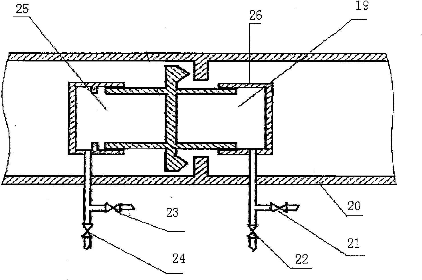
The invention relates to an inherent safety tube-pool type nuclear reactor for research. The cooling-water main pump and the after-heat deriving pump of the reactor are set at back of the main heat-exchanger and connected in parallel in the main circuit room. The after-heat heat-exchanger is fitted in the water pool of the reactor. The main circuit room is provided at upper part of the water pool and at the bottom of the main circuit room there is a pipeline communicated to the under-water part of the water pool. At the inlet and the outlet of the reactor core is respectively provided with a hydraulic control open-close valve communicated with the water pool of the reactor. When the main pipeline occurs water-loss fault, water in the main circuit room can return to the water pool. At same time, as the pressure in the reactor container is low, the hydraulic control open-close valves at inlet and outlet of the reactor core automatically opens. When the after-heat deriving pump occurs fault, the inlet-outlet hydraulic control open-close valve is opened by a signal of high reactor-core temperature to make the reactor core and the water pool form a natural circulation to derive the after heat of reactor core into the water pool of the reactor.

Description

technical field [0001] The invention relates to a nuclear reactor, in particular to a multifunctional research reactor and a tool pile for testing fuel and materials. Background technique [0002] For multifunctional research reactors and tool piles for testing fuel and materials, the intrinsic safety and passive safety systems shall be fully considered. For the research-type tube-pool reactors that have been built, there are some imperfections in view of the existing safety standards. For example, the direction of water flow in the core of JMTR in Japan, ATR in the United States, and HFETR in China and CARR research reactors in China is from top to bottom, and there is a flow reversal process after the core is cut off; there is no second shutdown system; the waste heat export system is Active, reliable Power supply failure or failure of the waste heat export pump to start will cause serious consequences; in the event of main pipeline rupture and water loss (before the main...

Claims


Application Information

Patent Timeline
Patent Type & Authority Patents(China)
IPC IPC(8): G21C15/18
CPCY02E30/40Y02E30/30
Inventor 吴英华丁晓亭牛文华
Owner NUCLEAR POWER INSTITUTE OF CHINA
Learn More