
Press machine

A mechanical and pressure technology, applied in the direction of presses, stamping machines, forging presses, etc., can solve the problems such as the inability to adjust the height of the slider, achieve the effect of good sliding action, improved versatility, and long life

Inactive Publication Date: 2010-01-06
KOMATSU LTD +1
View PDF6 Cites 0 Cited by
  • Summary
  • Abstract
  • Description
  • Claims
  • Application Information

AI Technical Summary

Problems solved by technology

Therefore, in a press machine that requires high-precision press processing, if a structure such as the above-mentioned forging press device is adopted in order to reduce the overall height of the press machine, the height of the slider cannot be adjusted, and there is a problem that the press cannot be performed with high precision. processing problem

Method used


Image

  • Press machine
  • Press machine
  • Press machine

Examples


no. 1 approach

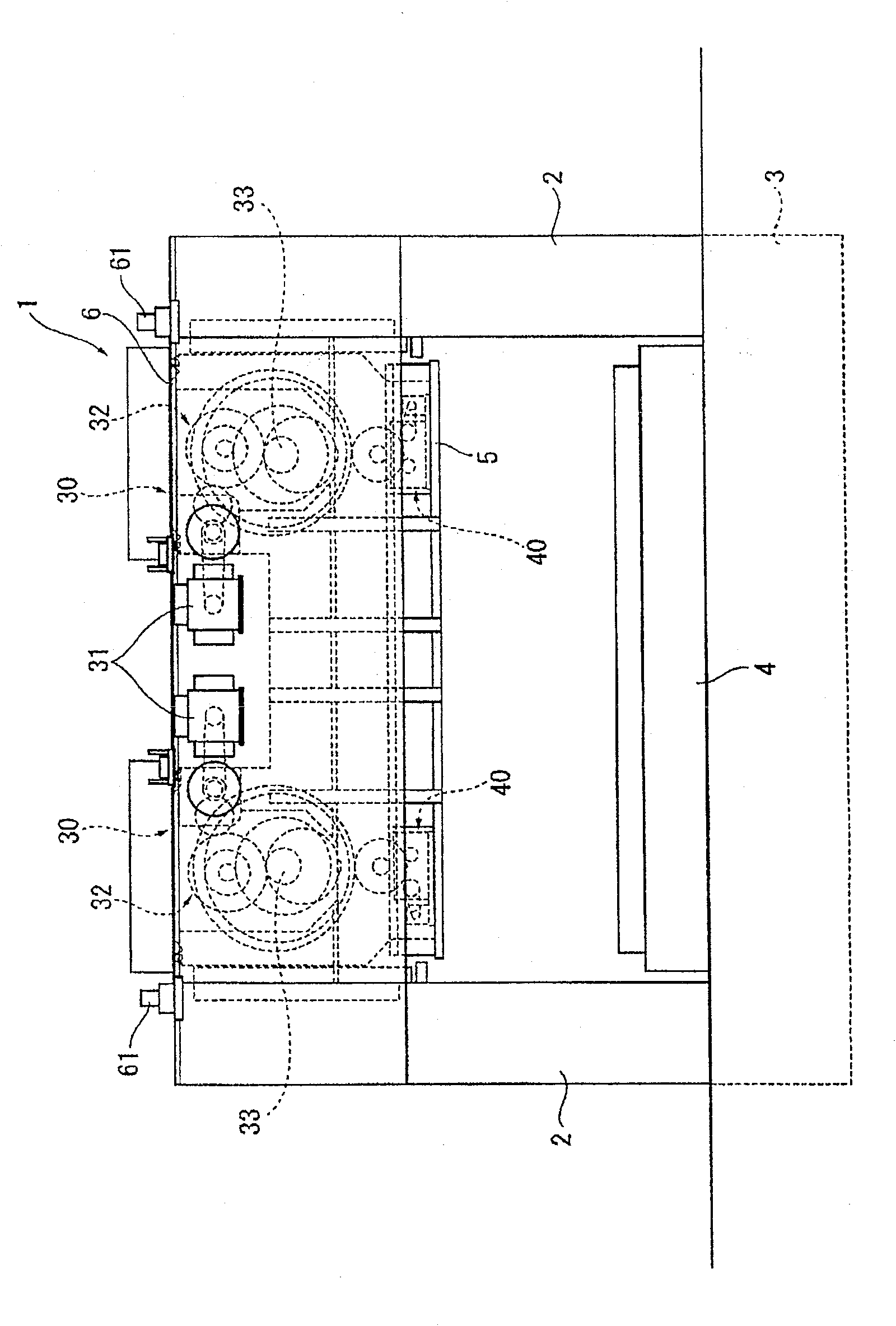
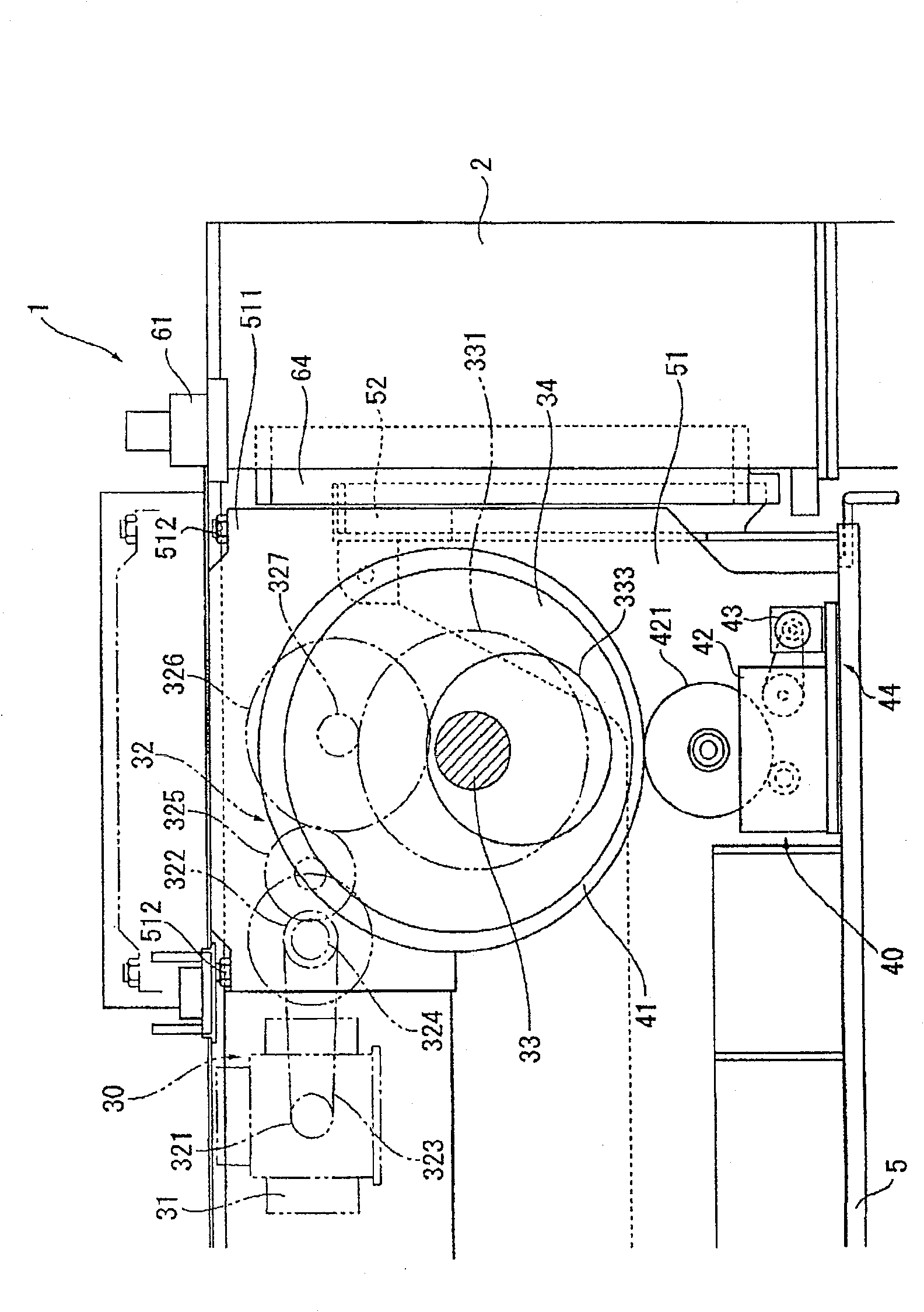
[0029] figure 1 It is an overall view showing a servo press (press machine) 1 according to the first embodiment of the present invention. in figure 1 In the figure, the left side of the figure is the front of the servo press 1, and the right side of the figure is the back of the servo press 1. As that figure 1 As shown, in the servo press 1, four columnar uprights (only two shown) 2 are erected on the upper surface of the base 3, and the upper part of the base 3 is placed in a manner surrounded by 4 uprights 2 Bolster 4. A crown 6 is provided on the upper part of the column 2. In addition, a tie rod 61 is used to fasten and connect the beam 6, the column 2, and the base 3 in a thorn-like manner. A slider 5 is supported on the cross beam 6, and a slider driving device 30 that moves the slider 5 up and down (lifting operation) is also provided.

[0030] If the slider 5 moves up and down under the action of the slider driving device 30, the workpiece is subjected to press process...

no. 2 approach

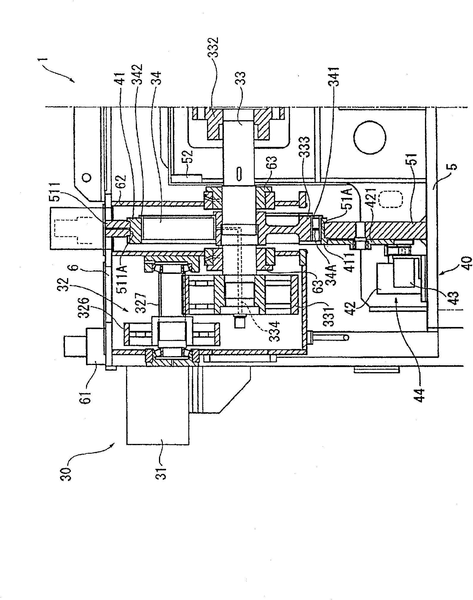
[0064] Next, the second embodiment of the present invention will be described. The second embodiment is the same as the first embodiment except that the installation structure of the rotating ring 34 and the adjustment ring 41 of the servo press 1 of the first embodiment is different from that of the first embodiment.

[0065] Image 6 An enlarged view of the slider driving device 30 of the servo press 1 of the second embodiment is shown. In addition, Figure 7 An enlarged side sectional view of the slider driving device 30 is shown. Like these Image 6 and Figure 7 As shown, the rotating ring 34 of the slider driving device 30 is mounted on the eccentric drum 333 through a spherical roller bearing (rolling bearing) 343. In addition, the adjustment ring 41 is attached to the rotating ring 34 via a cylindrical roller bearing (rolling bearing) 344. In addition, the combination of the spherical roller bearing 343 and the cylindrical roller bearing 344 is adopted in consideratio...


PUM


Abstract

A press machine, wherein a rotary ring (34) having an outer periphery eccentric to an inner periphery is installed on the outer periphery of an eccentric drum (333) on an eccentric shaft (33). An adjusting ring (41) having an outer periphery eccentric to an inner periphery is installed on the outer periphery of the rotary ring (34), and a slide (5) is installed the outer periphery of the adjusting ring (41). Since the slide (5) and a slide drive device (30) are overlappingly disposed at a roughly same height, a distance between the slide drive device (30) and the lower end of the slide (5) can be reduced and the overall height of a servo-press (1) can be reduced. Also, since the height position of the slide (5) can be fine-adjusted by rotating the adjusting ring (41), the press machine can accurately perform press working.

Description

Technical field [0001] The present invention relates to a press machine, and particularly to a press machine that performs press processing requiring high precision on sheet metal, for example. Background technique [0002] Conventionally, as a press machine, there is a forging press device that converts the rotational motion of a crankshaft into a lifting motion of a slide to perform forging (for example, see Patent Document 1). The forging pressure device has a swing rod that passes through the crankshaft. The upper end of the swing rod is supported on the slider by a shaft and can rotate freely. In addition, an arc-shaped surface centered on the shaft is formed at the lower end of the swing lever, and the slider is arranged in contact with the arc-shaped surface through a liner. [0003] In this forging press device, when the crankshaft rotates, the swing rod swings around the shaft rod and simultaneously causes the slider to move up and down. According to this configur...

Claims


Application Information

Patent Timeline
Patent Type & Authority Patents(China)
IPC IPC(8): B30B15/06B30B1/26
CPCY10T74/18208B21J9/18B30B1/266B21J9/02B30B1/263
Inventor 马场清和关晴二渡边圣司铃木裕一
Owner KOMATSU LTD
Learn More