
Slide fastener slider with automatic locking device

An automatic locking and zipper technology, which is applied in the field of zipper sliders, can solve the problems such as the inability to fully exert the locking function of the sliders, damage, and the small gap of the locking claws.

Active Publication Date: 2009-12-23
YKK CORP
View PDF7 Cites 2 Cited by
  • Summary
  • Abstract
  • Description
  • Claims
  • Application Information

AI Technical Summary

Problems solved by technology

As a result, there is such a problem that the sewing thread that sews the fastener element to the fastener tape may be damaged, or the gap into which the locking claw is inserted is very small, so that the locking function of the slider cannot be fully exerted.

Method used


Image

  • Slide fastener slider with automatic locking device
  • Slide fastener slider with automatic locking device
  • Slide fastener slider with automatic locking device

Examples


no. 1 example

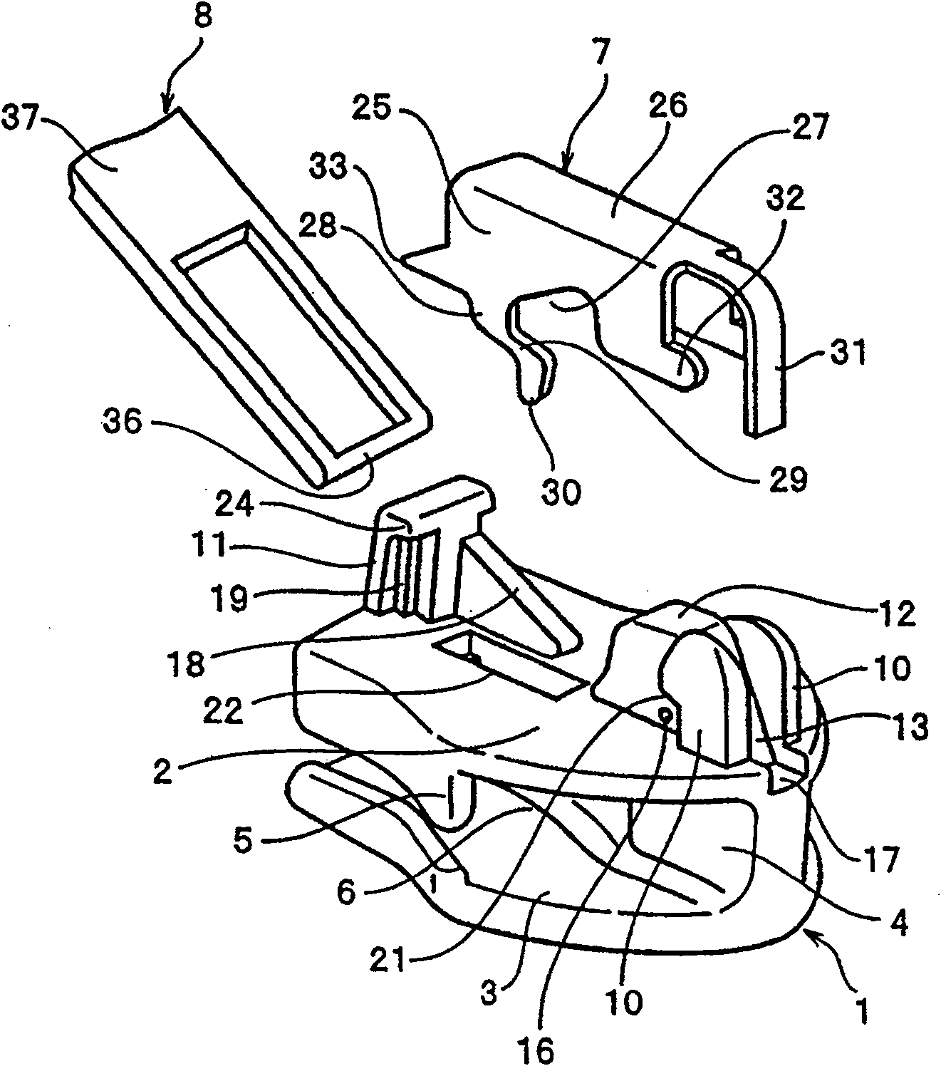
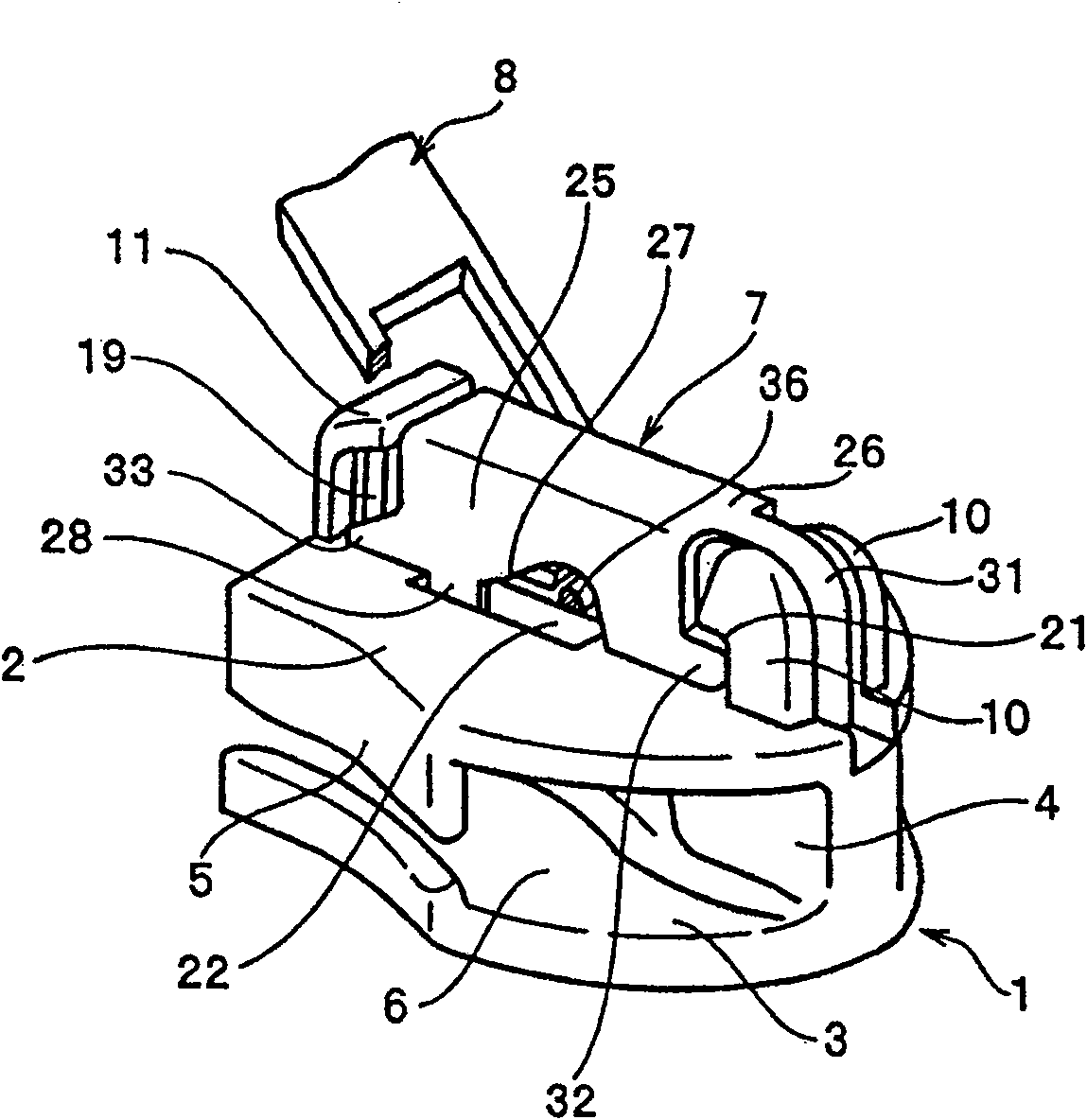
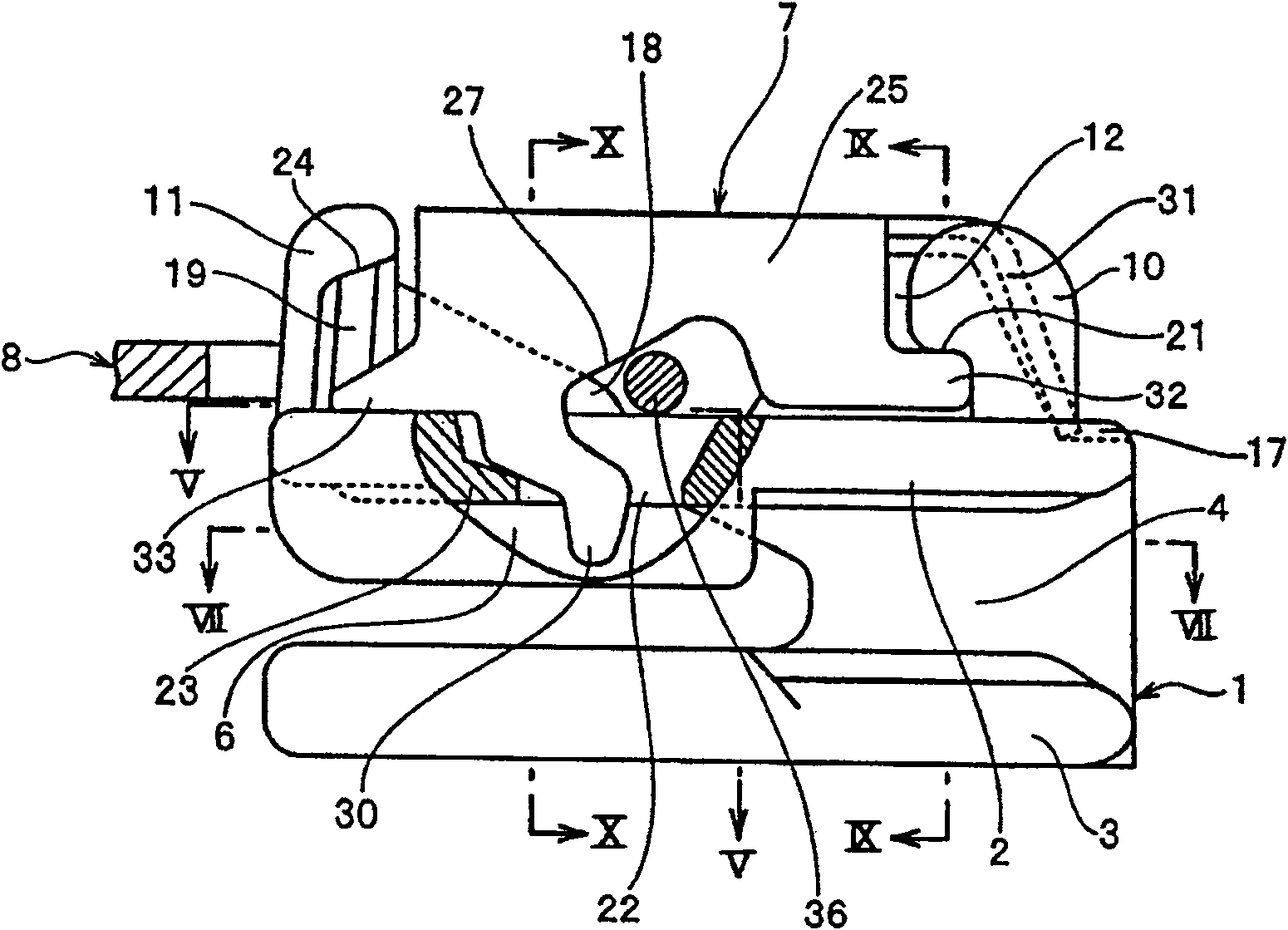
[0040] in accordance with Figures 1 to 9 In the zipper slider with automatic locking device of the first embodiment shown, the main body 1 and the pull tab 8 are formed by die-casting method with metal such as zinc alloy, aluminum alloy, and the cover 7 is formed by stamping steel sheet. The slider with an automatic locking mechanism includes three parts, namely, a main body 1 , a cover 7 and a pull tab 8 . The cover 7 is equipped with locking claws 30 as a locking mechanism, and by operating the pull tab 8, the locking claws 30 can be inserted between the left and right zipper elements 40 arranged in a straight line. A pull tab 8 prepared by a user may be used as the pull tab 8 used here. Therefore, the slider with the automatic locking device can be easily assembled by hand.

[0041] like figure 1 As shown, in the slider body 1 , the upper wing plate 2 and the lower wing plate 3 are connected with rhombus blocks, and flanges 5 are formed on the two side edges of the upp...


PUM


Abstract

The invention provides a slide fastener slider with an automatic locking device comprising: a pawl hole (22) in which a locking pawl (30) can be inserted is provided in a top surface of a body (1) of the slider; front attaching posts (10) and a rear attaching post (11) are provided in front of and in back of the pawl hole (22); a cover (7) comprises front engaged portions (32) which engage the front attaching posts(10) and rear engaged portions (33) which can move vertically within the rear attaching post (11); an elastic piece (31) having an elasticity is provided at a front end of a top wall (26) of the cover (7) such that it opposes the front attaching posts (10); opening portions (27), which allow a pivot shaft (36) of a pull-tab (8) to pass through, are provided in side walls (25) on both sides of the cover (7); a proximal portion (29) of the locking pawl (30) is arranged on a rear side of at least one of the opening portions (27); and the proximal portion (29) is bent so that a front end of the locking pawl (30) is located on a forward side, thereby attaching the cover (7) and allowing the locking pawl (30) provided on the cover (7) to be inserted easily into an excess gap between linear fastener elements without damaging sewing yarns or the like.

Description

technical field [0001] The present invention relates to a zipper puller with an automatic locking device, in particular to a zipper puller with an automatic locking device which can actuate a cover with locking claws by pulling a pull piece to exert a locking function. Background technique [0002] In general, the following zipper pull with automatic locking device is already known as described in US Pat. No. 2,657,445. In the cover 107 that is constructed between the cover attachment posts standing upright at the front and rear positions of its slider body, as Figure 11 As shown in the developed view of the front attachment post, the elastic piece 131 fixed to the front of the front attachment post is protrudingly provided, and the engagement piece 150 that can be swingably attached to the front attachment post is provided under the base portion of the elastic piece 131 . An engaging piece 150 swingably attached to the rear attachment post is provided at the other end, th...

Claims


Application Information

Patent Timeline
Patent Type & Authority Patents(China)
IPC IPC(8): A44B19/30
CPCA44B19/306
Inventor 岩濑裕一
Owner YKK CORP
Learn More