
Business intercommunication test method and device for asynchronous transferring mode exchange

A test method and test device technology, applied in the direction of data exchange network, data exchange through path configuration, digital transmission system, etc., can solve the problems of heavy software modification workload, missing test, high cost of batch test, etc., and achieve high efficiency The effect of automated testing

Inactive Publication Date: 2009-12-02
HUAWEI TECH CO LTD
View PDF3 Cites 0 Cited by
  • Summary
  • Abstract
  • Description
  • Claims
  • Application Information

AI Technical Summary

Problems solved by technology

[0006] ① The cost of the tester is too high. This is because the product is in the production duplication stage, and there are many similar products that need to be debugged. In this way, the cost issue must be carefully considered, so the cost of batch testing is very high
[0007] ②The ATM ports supported by many testers are limited, and the optical fiber needs to be plugged and unplugged many times during the test, which reduces the test efficiency and is not suitable for the test requirements of mass production
[0008] ③ The intervention of external instruments requires a corresponding improvement in the quality of testers, which virtually increases the cost of manpower
[0010] ①The rate of sending SAR packets is limited, it is difficult to reach the rate supported by the switching channel, and it cannot test the performance such as the function of the back pressure mechanism of the network board
[0011] ②Because the SAR chip of the control board sends the contract to the physical port, it only covers the switching channel belonging to the currently tested I / O board, and the cross channel of the network board cannot be tested (if the cross channel is supported, the software modification workload is huge), There is a missing test problem, and obviously the coverage cannot be guaranteed

Method used


Image

  • Business intercommunication test method and device for asynchronous transferring mode exchange
  • Business intercommunication test method and device for asynchronous transferring mode exchange
  • Business intercommunication test method and device for asynchronous transferring mode exchange

Examples


Embodiment Construction

[0029] The present invention will be described in further detail below through specific embodiments and in conjunction with the accompanying drawings.

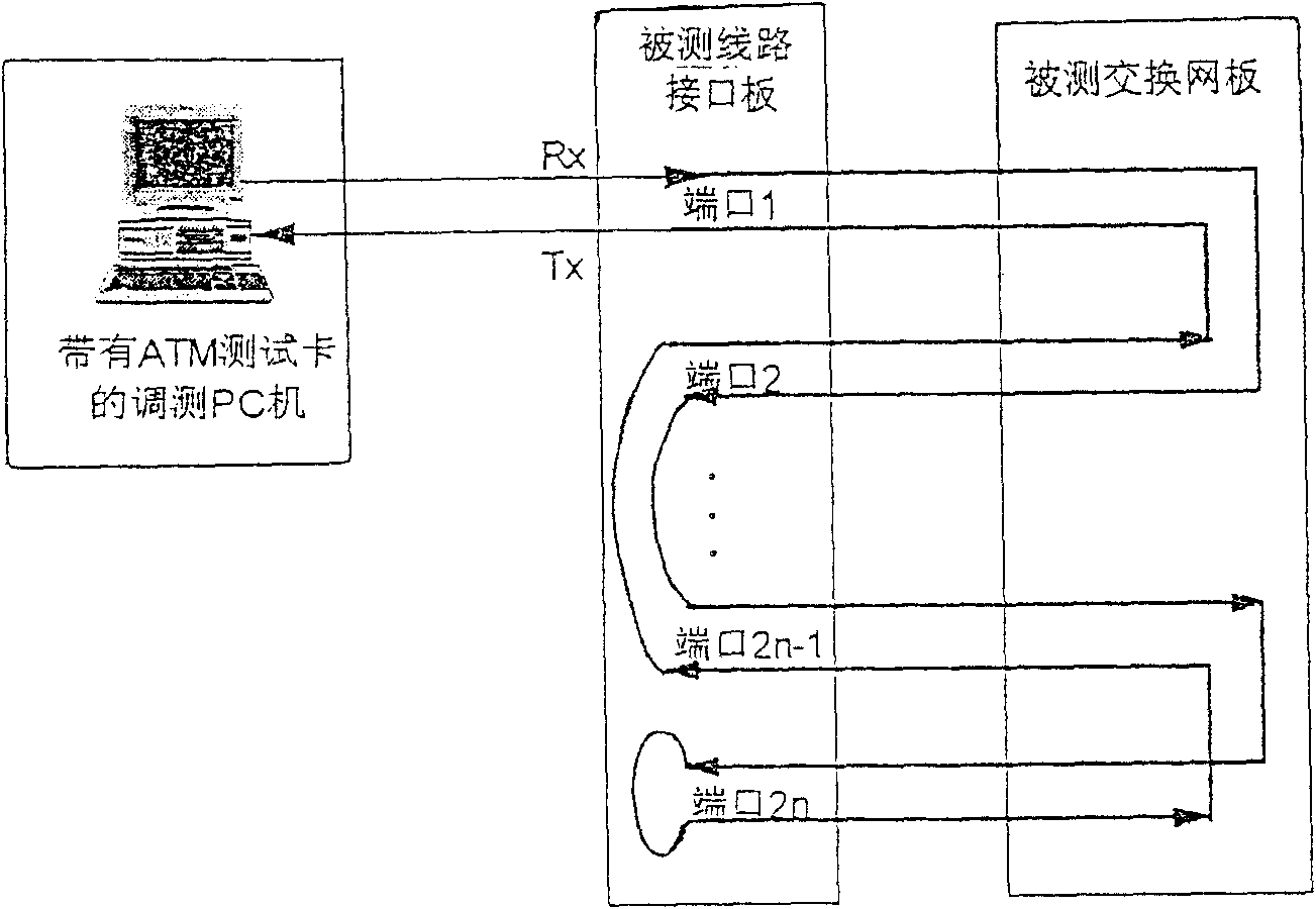
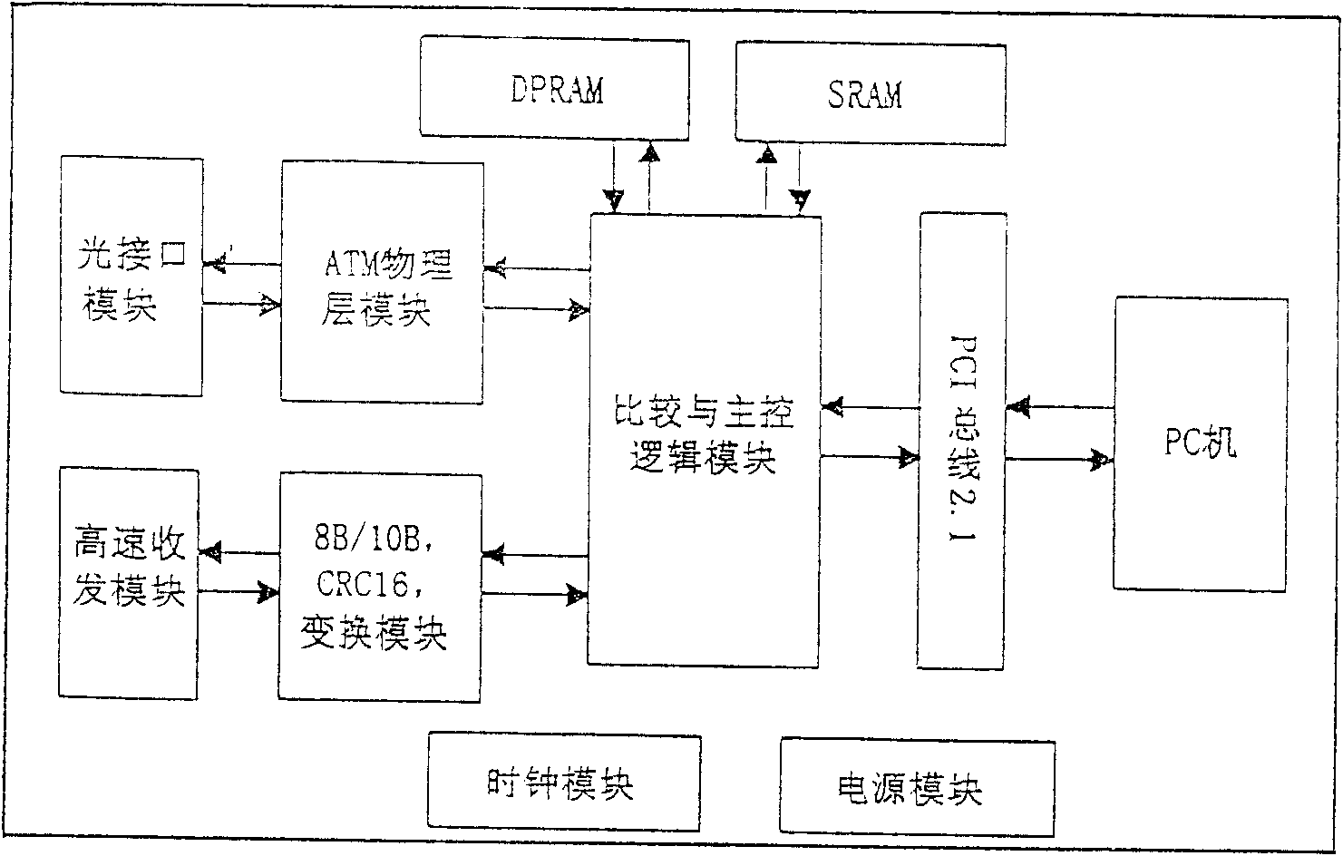
[0030] See figure 2 , the program only needs a PC computer, an ATM test card designed and developed by itself, the ATM switch to be tested, and several cables. The test card can be inserted into a PC computer, and can provide high-speed (155M / 622M / 2.5Gbit / s) service flow, test the bit error rate of each port of the switching network board, and count the number of sending and receiving and error cells. Based on the hardware of the card, related software has been developed to realize the functions of generating, sending, receiving, counting, comparing and reporting errors, and setting the working mode of the test card.

[0031] Such as figure 2 As shown, according to the figure, use a cable that meets the electrical characteristics of each port to send and receive an external loopback between this port and the next port, and...


PUM


Abstract

The invention discloses a service interworking test method and device of an asynchronous transfer mode switch, which allows the test service flow to traverse all switching channels, and finally compares the final service flow received by the ATM test card with the initially sent service flow, counts and judges the number of cells Lost, wrong data, and report the test results. It solves the problem of the test data source of the business flow of high-speed cells, and can carry out high-load business tests on the whole switch; the business flow (cell) generated by the test device can be switched to any channel, so it can be tested to the network board Cross-channel, there is no missing test; the ports that need to be connected during the test only need to be plugged and unplugged at one time, breaking through the test obstacles inherent in the test object with many test channels and high data transmission rate, and realizing high-efficiency automatic testing.

Description

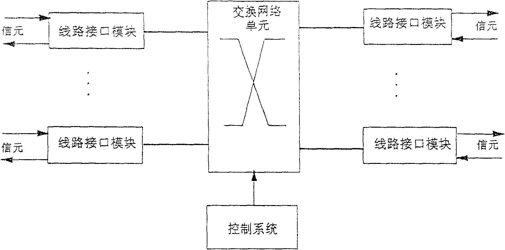
Technical field: [0001] The invention relates to a method and a device for testing service interworking of an asynchronous transfer mode (ATM) exchange. Background technique: [0002] With the continuous increase of transmission rate and switching capacity, the design of ATM broadband switches has become increasingly complex, so the production test of this kind of broadband switching products is also facing increasingly severe challenges, and the most difficult and most important in the production system level test The most important is the business interoperability test, which is to test the business interoperability between each board of the product, and also to test the switching capability of the entire switch. This test item is a key point for a comprehensive inspection of the entire ATM switch before delivery, and its significance can be imagined. [0003] Such as figure 1 As shown, the ATM broadband switch has three parts: the switching unit, the interface unit and ...

Claims


Application Information

Patent Timeline
Patent Type & Authority Patents(China)
IPC IPC(8): H04L12/40H04L12/26
Inventor 林五四
Owner HUAWEI TECH CO LTD
Learn More